Bevel System Type (Default: Kinetic Versatile)
No Bevel Installed
Kinetic Versatile- Kinetic's standard hollow, infinite windup plasma/flame bevel, which allows the bevel or flame tool to be mounted within it, and allows infinite rotation.
Oblique Axis- Supports two tilted axes, as used on Kinetic's waterjet bevel.
Bevel Azimuth Offset (Default: 0)
Touchcut defines a bevel azimuth angle of 90 degrees when the the machine is cutting a positive bevel along the positive X axis, ie it uses the path normal direction. Other machines may define this differently, this setting is used to compensate (in degrees).
Bevel Angles Preconfigured Before Pierce (Default: False)
If the torch is oriented by instructions prior to or during the pierce, we don't need to add a G1 line after the start to set initial angles. Set to True if this is the case.
Include Bevel Words Even If Unchanged (Default: False)
Normally the bevel Angle and Azimuth words are skipped if there is no change to them. This forces them to be written regardless.
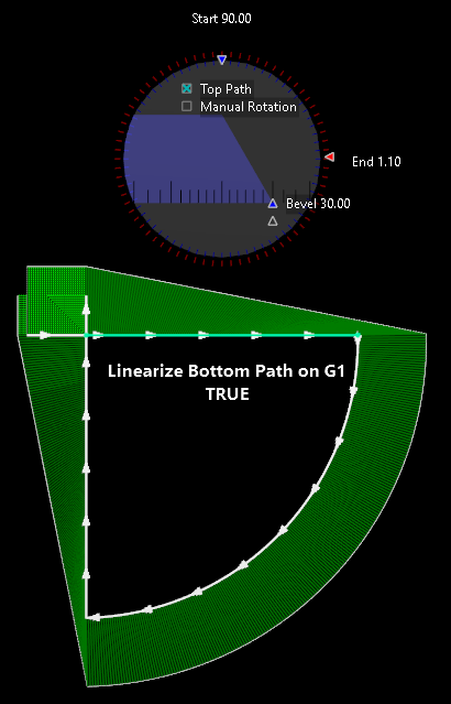
Linearize Bottom Path on G1 (Default: True)
Only affects how Primecut displays bevels with varying azimuth on linear segments; does not affect program generation.
Touchcut controllers always linearize the bevel angle bottom path offset (ie thickness * tan(bevel angle) ) on linear transition bevels, so that the bottom edge of a transition bevel is straight. Even if the azimuth (Bevel Rotation) angle varies along the linear segment, Touchcut again calculates start and end points, and creates a motion that generates a straight line bottom path. This produces nice looking miters on corners, clean corner loops etc.
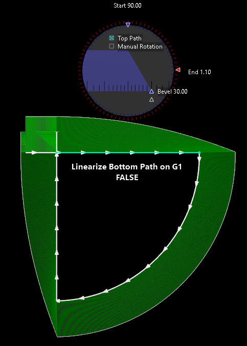
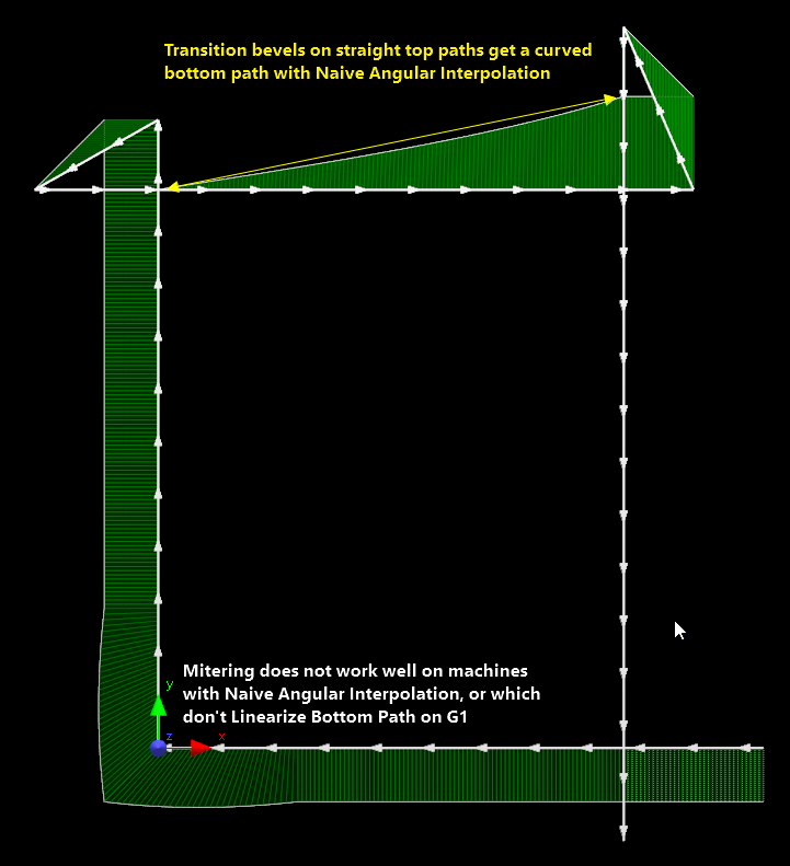
Some controllers may instead simply interpolate the requested angle change across the segment length "Naive Angular Interpolation" , which will result in a curved bottom path, and strange looking Miters.
Only affects how Primecut displays bevels with varying azimuth on linear segments; does not affect program generation.
Primecut Mitering of bevel corners does not fully support machines which do not Linearize Bottom Path on G1
With this setting turned off, Primecut interpolates the bevel and azimuth angles along a linear segment, generating multiple arcs if necessary to represent the bottom path.
Regardless of the state of this setting, the bottom path on arcs (G2,G3) is not linearized and follows explictly what the G codes tell it to do, ie both Touchut and Primecut always use Naive Angular Interpolation on arcs.
Here is a (somewhat academic!) part where the programmer has set large changes in azimuth angle (bevel rotation) on the bevel on the arc (10 turns) and the left edge (3 turns), possibly to create a serrated effect. There is no "serration" on the left edge the default Linearize Bottom Path on G1 setting (True) on the bevel tool is in effect:
")
Linearize Bottom Path on G1 TRUE (Default)
This is appropriate to Touchcut controllers; we can see the resulting path used by Touchcut is the same:

Touchcut Toolpath: G1 on left is linearized.
(In order to achieve the serrated effect with Touchcut, you could split the single left line up into many small segments after setting the bevel rotation values, using Break Bevel Segment)
If the setting is set to false, as might be appropriate for other controllers, then Primecut will display the process as :

Linearize Bottom Path on G1 FALSE
This setting only affects the display in Primecut, so as to have it realistically depict the result seen at the machine. It does not affect G-Code output, regradless of the setting the codes output for this part are:
(Bevel)
T2(400A O2 Air)
G0X137.1269Y143.0712
G41D21
M30
G1A30.R90.
G1X30.
G1X137.6731
G42D21
G1A10.R1.1
G41D21
G2X-137.6731Y-143.0712I-140.3752J-2.6961R3600. (10 Turns)
M61
G42D21
G1Y-0.4073R180.
G41D21
G1Y0.4073
G1Y143.0712R1260. (3 Turns- but controller some controllers such as Touchcut will interpret it as none)
G1A30.R180.
G1Y20.
M3
Another example, showing bevel azimuth changes along the top and left edges:
|
|