Generating Geometry From A Solid ModeL
The following steps are what we used generating a 2D DWG from Solidworks with geometry we could then cut with Primecut; the instructions should apply with some modification to other solid modeling packages.
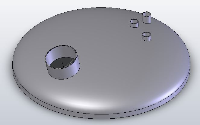
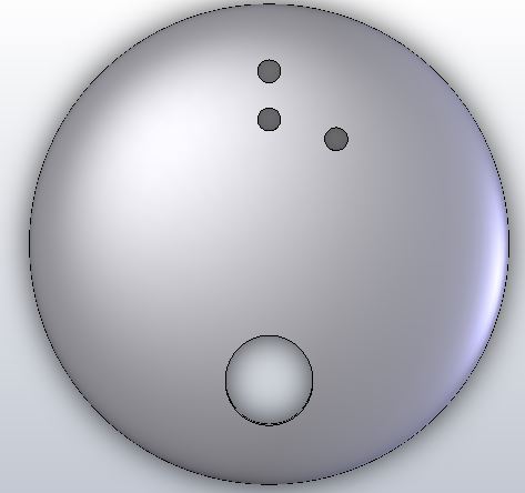
1.Draw the dome; typically a revolve of a sketched cross-section of the dome. For a torishperical dome this is large arc for the main dome and a smaller arc joining it tangentially for the knuckle.
2.Intersect the objects passing through the dome (“penetrations”) to produce cutouts.
3.Rotate the model so the view is down from above, and create a drawing.
4.Export the drawing as a DXF or DWG for import into Primecut.
NOTE
When creating the drawing, you should first decide if the weld prep is to be applied inside the dome, in which case the top surface intersection is all that is required, or if the weld prep is to be applied to the top, in which case it is the intersection with the bottom of the dome that we want, and we should generate the drawing with hidden detail if there are any oblique penetrations (penetrations whose axes are not co-axial with the tank). If in doubt, or there is a mixture, include the hidden detail anyway. We can pick and choose what we want to process in Primecut.
Processing it in primecut
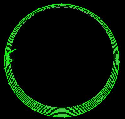
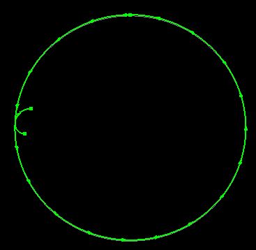
Select the geometry carefully, again if applying weld prep to the top face we want to process the path representing the bottom geometry, otherwise the path representing top geometry. If hidden detail has been included in the drawing you may find overlapping “circles” for coaxila penetrations- Primecut did not see them as duplicates because they are represented in the export as splines and have different control points- in this case it is easiest to delete one of each pair of duplicates using Alt-selection.
If hidden detail has not been exported you may still see some of the bottom intersection if there are oblique penetrations as in this case- simply delete or ignore the “semicircle”

1.Ensure after loading the drawing that the part origin (0,0) is at the center of the dome.
2.Process the selected path with the bevel tool, and create suitable sized leadins and leadouts if required. Do not worry about setting a bevel angle yet.
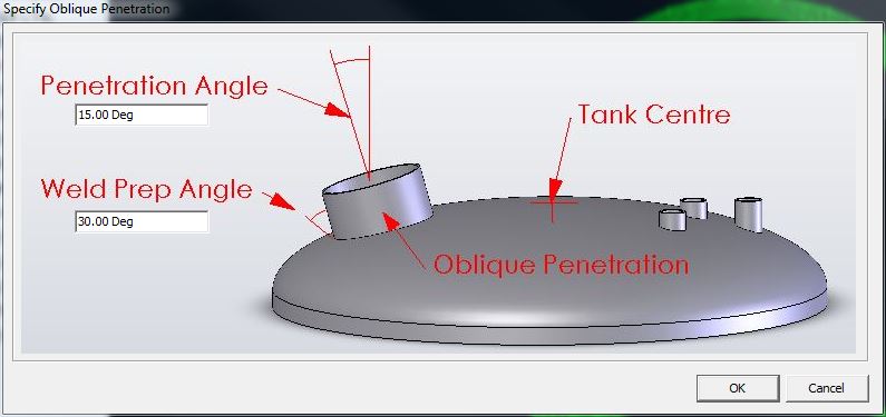
3.Select the resulting bevel process and use the Dome Penetration Tool from the right-click context menu to define the penetration angle and weld prep yoiu require. The penetration angle is defined from vertical in a plane defined by the penetration axis and the dome center (0,0). Use a positive weld prep angle if the weld prep is applied to the top of the dome, or a negative weld prep if it is applies to the bottom.
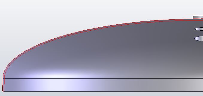
The resulting bevel paths show a variable bevel angle around the cut: