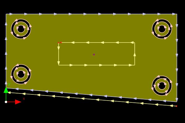
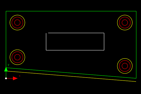
Introduced in Primecut version 4.131.540, this mode in the Geometry Editor allows parts to be displayed in a closer visual style to how they were drawn in CAD, especially if drawn in AUTOCAD or one of the many packages that emulate it.
There is a Show As CAD button in the main geometry editor toolbar to switch between standard and CAD display modes.
We can compare this mode to Primecut's "standard"geometry display mode:
|
Standard Display |
Show As CAD |
Example |
|
|
Colors |
Closed External paths BLUE Closed Internal path RED Open Paths YELLOW |
Colors are shown as drawn. Entities support BYLAYER coloring |
Path Direction Arrows |
Paths show their direction with arrows |
No arrows |
Path Fill |
Parts are displayed filled |
No fill |
Dangling Endpoints |
Highlighted with red dots |
No endpoint highlighting |
Use For |
Identifying drawing problems, controlling pathing |
Discussing drawings with drawing suppliers, mapping colors to tools, advanced CAD editing with Layers. |
See also Working With Layers.

