The part we will use for this tutorial has a number of geometric errors. It is unlikely that you will encounter parts with this many errors on a regular basis. If you do, it is an indication that the CAD operator needs to be made aware of the situation.
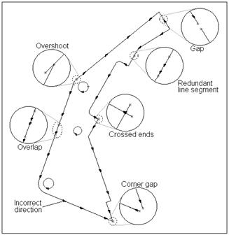
When a part is imported PrimeCut will join ends that are less than 0.1mm / 0.004" apart. On this part the distances are intentionally greater than this, and so it will be loaded as shown above.
1Open the Workorders mode.
2Create a New Workorder ![]() .
.
3Select Tut Customer 1 as the customer, leaving the default invoice number. If no invoice number is showing enter a random number.
4Click Import Part ![]() .
.
5Navigate to the NE Tutorial parts folder which should be found (in a standard installation) in C:\Program Files\PrimeCut4\NE Tutorial Parts.
6Select Broken_Part_1.dxf and Open it. If the file is not showing up, make sure "Files of type:" is set to "Drawings (*.dxf, .*dwg)" in the file explorer.
7Enter the following properties in the dialog box. Under Number Required enter 1, under Name type BrokenPart followed by your initials (to avoid double ups from past tutorial users), under Material select Mild Steel, under Thickness select 16mm.
8Double click on the Broken_Part_1 part in the parts selector window on the left to bring up the part editor.
9Click on the Geometry editor tab at the top of the screen.
PrimeCut makes the problems visible by drawing red squares at the end of each segment. This makes it easy to zoom in on the area and determine the nature of the problem.
This tutorial is split into sections that may be useful on their own if you encounter these problems in the future. For this reason each section can stand alone to some extent. The downside to this is that some tasks are repeated. In a real situation for example you would explode the segments only once, fix a number of problems then join them again.