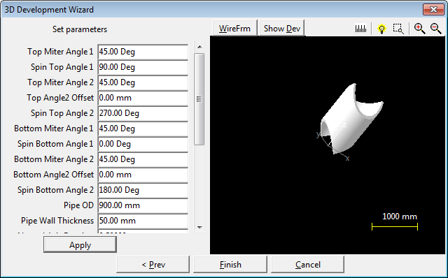
The ends of a pipe can be cut to fit multiple flat sheet shapes using the compound mitered pipe wizard.

Miters at the top end of the pipe.
Top Miter Angle 1 specifies the angle of a flat cutout through the top end of the pipe.
Spin Top Angle 1 allows the cutout to be rotated around the center line of the cylinder.
Top Miter Angle 2 specifies the angle of a second flat cutout through the top end of the pipe.
Spin Top Angle 2 allows the second cutout to be rotated around the center line of the cylinder.
Top Angle 2 offset changes how far from the end of the pipe the cutout occurs.
Miters at the bottom end of the pipe.
Bottom Miter Angle 1 specifies the angle of a flat cutout through the bottom end of the pipe.
Spin Bottom Angle 1 allows the cutout to be rotated around the center line of the cylinder.
Bottom Miter Angle 2 specifies the angle of a second flat cutout through the top end of the pipe.
Spin Bottom Angle 2 allows the second cutout to be rotated around the center line of the cylinder.
Bottom Angle 2 offset changes how far from the end of the pipe the cutout occurs.

Neutral Axis Fraction should be set to 0.5 if developing the pipe from flat plate otherwise 0.0 if cutting pipe.
Dev. Segs the number of segments around the diameter that the pipe will be broken up into.
Development Start Angle the point on the unrolled cylinder that will match up with the edge to be joined on the flat plate.
Show bends When viewing the flat plate development view the bend line of each segment.