SmartCluster: Common Line and Common Crop Cutting now provides an easier way to do Commonline Cutting.
To save cutting, and to avoid thin skeleton pieces, it is sometimes necessary for two parts to share a common cut line. This tutorial shows how this can be achieved.
1Open the Nesting mode.
2Click Open parts from database ![]()
3Search for Parts that have 'Common Line Cutting' as their workorder invoice number (make sure to select "Show All" and "All Cut By Dates"). Open them all.
4Click Open Plate ![]()
5Click Create New Plate ![]()
6Enter the following details
Plate Material |
GR250(A36), 20.00mm |
Length |
4000mm |
Width |
2000mm |
Click Add to Stock, and Close.
7Double-click on the plate in the plates explorer on the left to open it on the main screen.
8Drag the 4HoledPlate part onto the screen and create a 2 by 2 array, by using the array handle.
9Right click and click Create and Edit Cluster then click Create and Open. Click Close for the warning about affecting the nest.
10Select the CommonLine Cutting Tool. ![]()
11Enter the Kerf offset as 1.00mm
12Select the top line of the bottom left 4HoledPlate and then the bottom line of the top left 4HoledPlate. Click Create Join.
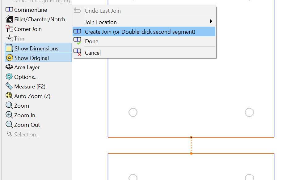
Alternatively you could have simply clicked on the second line twice as shown:
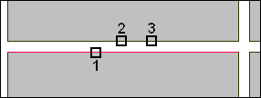
Figure 3: Joining Edges for Common Line Cutting
13Similarly, Select the top line of the bottom right 4HoledPlate and then the bottom line of the top right 4HoledPlate. Right Click and Click Create Join.
14Select the right hand side of the left grouping, and the left hand side of the right grouping. Right Click and Click Create Join.
15Right Click and Click Done.
16As you can see there are two horizontal internal paths, but only one vertical path. We will fix this by joining them.
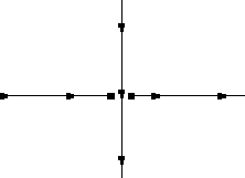
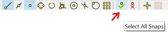
17Select the select all snaps button.
18Drag the right end point of the left line to the left end point on the right line.
19Holding down CTRL select both lines and Right Click. Select Join from the context menu to join the paths. Click Ok to accept the tolerance suggested.
There should now only be one horizontal line.
20Double-click on the plate in the plates explorer.
21Drag the custom rectangle and custom triangle onto the plate.
22Select them and right-click and select Quick Cluster.
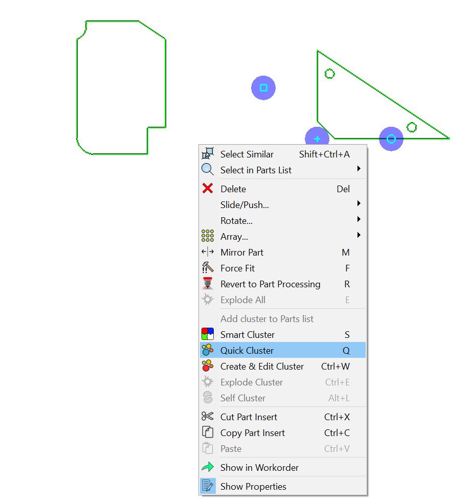
23Right click again and select Add Cluster to Parts list.
24Double-click on the cluster in the parts list to open it for editing.
25Select the Common Line Cutting Tool. Click Ok to set an offset of 1.00 mm.
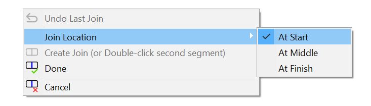
26Click again on the Common line Cutting tool and hold the mouse over Join Location. Click At Start.
27Select The Lines as shown.
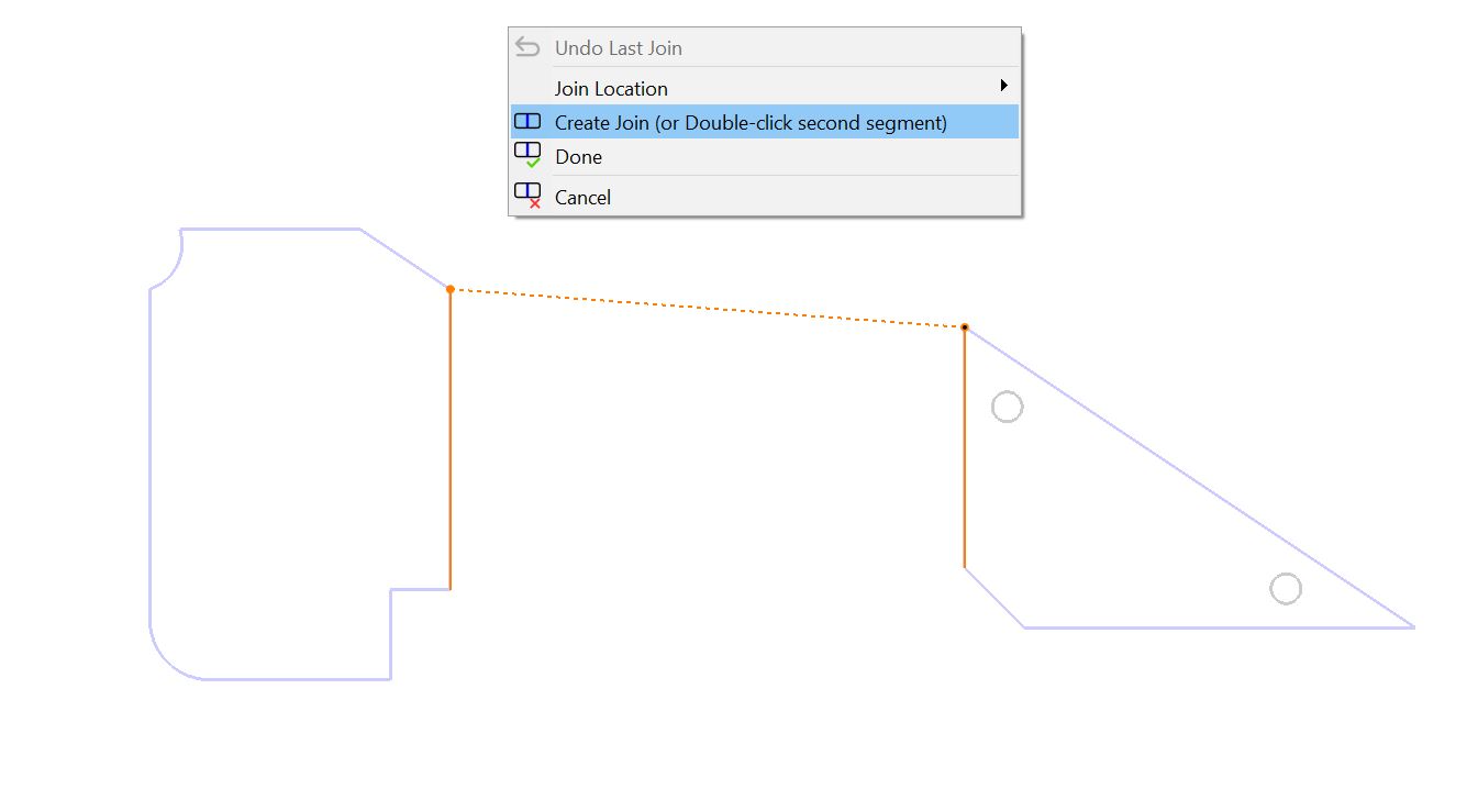
Note that you can select any two lines, even if they aren't parallel - the orientation of the second one will be adjusted so that they become parallel.
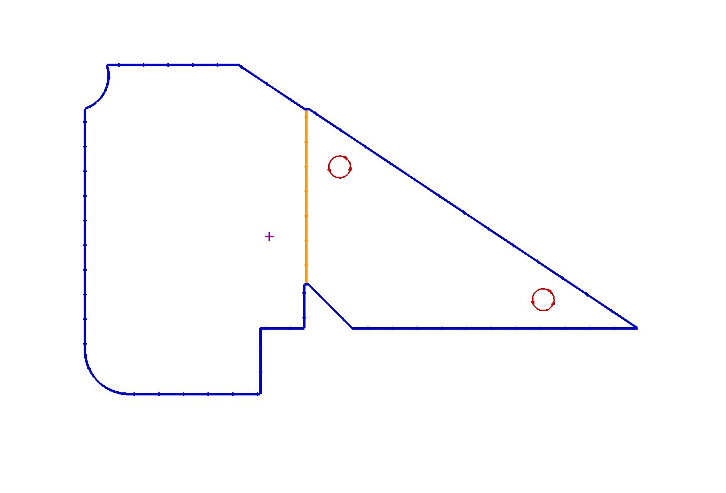
28Right Click and Click Create Join to join the paths
29Right Click and Click Done.
30Close the mode without saving.