SmartCluster: Common Line and Common Crop Cutting now provides an easier way to do common line continuous cutting of pairs, which can then be joined together to make a single continuous using a process similar to that described below.
Often you may have a large enough quantity of a perfectly rectangular or right angled triangular part, for which a right kerf cut is acceptable. Such cases warrant using a long continuous cut to cut them out, to save on machine time and consumables.
1Open the Workorders mode
2Search for and open the Continuous Cutting workorder. Hint, type Contin* to prevent miss-spelling from returning 0 results.
3Right Click the workorder from the workorders explorer and Click Open Workorder in Nesting.
4Click the open plate button ![]() and double click on one of the blank 3000mm by 2000mm, 5mm GR250(A36) plates to open it.
and double click on one of the blank 3000mm by 2000mm, 5mm GR250(A36) plates to open it.
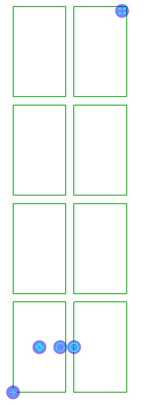
5Nest a 4 x 2 array as shown. If the array handles are obscured by the color of the part, change the color drop down list to Plain Color or No Fill.
6Right click with the array selected and click Create and Edit Cluster. Then click Create and Open.
7Click Close when it informs you that this will effect the nest.
8Click the CommonLine tool.
9In the box that opens enter a kerf offset of 1.5mm and click OK.
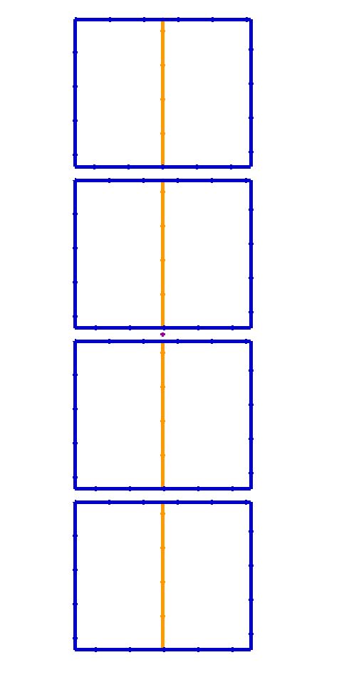
10Join the rectangles in pairs, selecting the right edge of the left side rectangle and double clicking on the left edge of the right side rectangle.
11Right Click and Click Done from the context menu.
12Select the outer paths of each pair of rectangles and Right-click and click the Offset Paths tool.
13Select an offset of 1.5mm and click OK.
14When asked if you want to keep the original entities click No.
15Press CTRL + A and Right click and click Explode from the popup context menu to explode all the closed paths.
16For each pair of rectangles:
1.Select the bottom edge and right click and click Divide Path from the popup context menu.
2.Enter 2 for the number of segments and click OK.
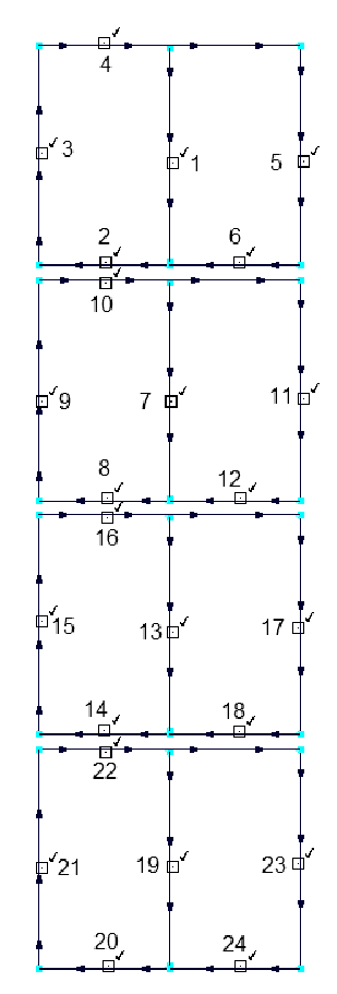
17Select the Corner Join tool and select the lines that compose the edges of the rectangles in the order shown below.
18Double click on the plate, in the plates explorer
19Click the Processing tab at the top of the screen
20Click the Process All button.
21For the open paths field make sure there is a leadin applied, of say 10mm. Click OK.
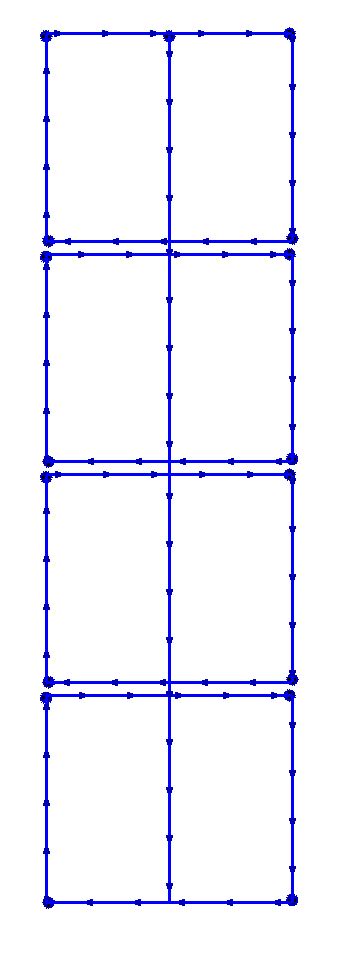
As you can see our array of rectangles will now be cut using a single continuous cut.
If you are doing this with right angle triangles then mirror (tick the mirror box in the properties window) each alternate pair of triangles, so that the intersections always have an even number of lines through them. Always do the center lines cut first.
22Close the mode without saving.