PrimeCut renders holes using applied spindle tool geometry, if it is available in the costing data. If not available, PrimeCut will render holes using the geometry provided in the drawing, ie the geometry the tool was applied to.
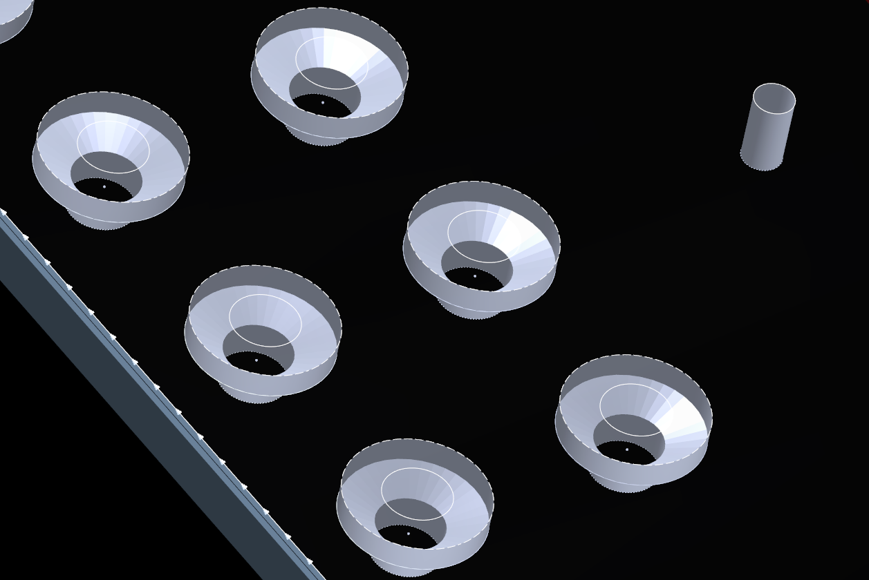
The primary drill data used for visualization is the bit diameter (Diameter 1), and if used on blind holes or as a counterbore/countersink then the tip angle (Angle 1) is also useful. In the image below we can see some counterbored holes, and the system is providing a realistic rendering of the finished holes, including the effect of the counterboring drill's tip angle.
If no tool diameter is found or is 0 in the costing data then the drawn diameter is used.
For example if a hole is drawn at 1", and a 1.5" drill, say "KSEM1.5000" is applied, the hole will be rendered 1.5" only if there is costing data on that material or a matching family for the bit "KSEM1.5000" and it has a non-zero Diameter 1; otherwise the hole will be rendered as drawn, as 1 1" hole. PrimeCut cannot automatically infer the diameter from the bit name as there are too many variables in how customers name their drills. We can however supply SQL queries which should update most costing data based on expression matching of the bit names.
For more information see Setting Up Spindle Tool Geometry