From Primecut v4.5.494, the software is more aware of drill bit diameter and tip angles. This has benefits in terms of how accurately drilling operations are rendered on screen ( and especially counterbored holes- see Drill Data and Hole Visualization), how accurately drill collision testing can be done, and how precisely thick plate prepiercing can be placed so the start is on the hole edge.
In order to simplify entry of this data which is likely not present, it is highly recommended to make use of material families- see Using Material Families.
The recommended procedure is this:
1.Create material families to group steels with similar machinability, ie those which will drill and machine at similar feeds. Try to make these families not overlap (ie each specific grade should appear in only one of these families) and cover all grades (ie all grades should be in these families).
2.Copy spindle data from the specific grades to the new families. If possible use the "least reliable" grade data first.
3.The families now contain the "authoritative" spindle costing data. Delete the spindle data from the specific grades to avoid data duplication.
4.Tool Geometry now needs to be set. Currently this is per grade (or family) which is not ideal and will be addressed in a future update.
5. For simple drills the main values needing to be set are D1 (tool diameter) and A1 (bit angle). For end mills and flat taps the tip angle is 180 degrees, however it can be left as 0, 180 will be assumed in this case. For KSEM drills the tip angle is typically 140 degrees. Users with consistent drill naming schemes can usually auto set tip angle and diameter on all their drills with a couple of SQL statements, see the example below.
Alternatively to SQL, this spindle data can be exported as a CSV, copied for other materials, and imported.
|
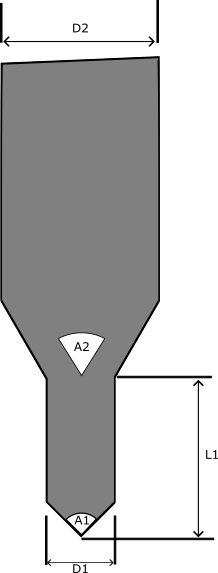
Where
D1 = Diameter L1 = Length 1 A1 = Angle 1 D2 = Diameter 2 A2 = Angle 2 |
Opening the Spindle Data window by double clicking a spindle for
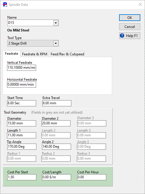
Note if a depth of 0 is given for a hole, then the drill through will be drawn as going the Extra Travel distance through the plate, for a Two stage drill it is important this be calibrated by the user to match the machine setting.
Example of SQL Setting of Diameters and Angles
Consider a user whose drills are all consistently named D10.0, D10.5, D12.0 , D14.0 etc and whose taps are M12, M14 etc. The following statement will update all the drill and Tap diameters:
UPDATE tblspindle SET D1=RIGHT(name,char_length(name)-1) where UPPER(name) SIMILAR TO '[DM][[:DIGIT:]]+.?[[:DIGIT:]]*'
The SIMILAR TO '[DM][[:DIGIT:]]+.?[[:DIGIT:]]*' means all specifiers beginning with D or M followed by 1 or more digits, then an optional decimal point, and some more optional digits
This is similar but is for a user whose drill diameters are specified in inches, and whose drills being KSEM... (eg KSEM1.5"):
UPDATE tblspindle SET D1=25.4*CAST ((substring(name from 5 for char_length(name)-5)) AS float) where upper(name) SIMILAR TO 'KSEM[[:DIGIT:]]+.?[[:DIGIT:]]*"'
Finally, the following sets all KSEM drill tip angles (not taps or mills) to 140 degrees (angles are stored internally in radians):
UPDATE tblspindle SET A1=(140*pi()/180) where upper(name) SIMILAR TO 'KSEM[[:DIGIT:]]+.?[[:DIGIT:]]*'