See also Change Plate
The Edit Plate button allows basic editing of plate geometry, particularly when adjusting remnants. The user must have permission to manage plate stock in order to access this function, to preserve the integrity of Primecut's stock inventory.
![]()
When Edit Plate is clicked, it "stays down" until clicked again, and the rest of the Edit Plate Toolbar appears. Here there are buttons to draw rectangles, circles and polylines on the plate. Shapes drawn either add to or subtract from the plate geometry. You can use the snaps to assist.
The undo button will undo all plate editing. Press Edit Plate a second time to exit Plate editing mode and commit the changes to the plate geometry.
Notes:
•All shapes drawn define an area, and thus are closed by definition.
•Use the snaps to assist with drawing, as well as the text entry boxes during shape creating to specify dimensions.
•You can use F8 (Ortho) to switch ortho mode on and off on the fly.
•You can only undo changes with the current plate edit, once Edit Plate is pressed a 2nd time to exit the mode, all changes are committed.
• There are 3 circle tools provided: Centre-radius, 2-point (diameter), and 3 point.
A skeleton plate is in stock, but the actual remnant has had the left hand corner cropped off.
1.Select the Edit Plate button
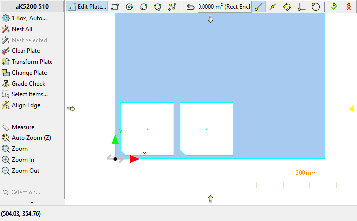
2.Click the rectangle button to draw the cropped corner. It helps to have the measurements of the cutout to draw this accurately. You can use the endpoint snaps to anchor the first corner to the bottom left corner of the plate, then you can use XD xxxx and YD yyyy to enter the width and height of the cutout respectively, or just indicate the top right corner with the mouse:
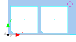
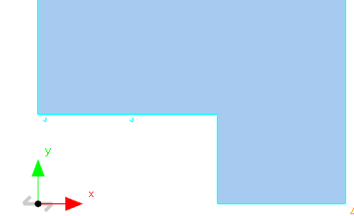
3.This results in the bottom left corner being removed, or actually "inverted" leaving the cutouts as plate sections. So we need to remove these also. Select the Polyline tool, and indicate each corner of the cutout (again ensure Endpoint Snap is on, also ensure you select the top left corner of the shape accurately, so you don't snap to the endpoint of one of the leads by accident). You can press C at the end to Close the polyline.
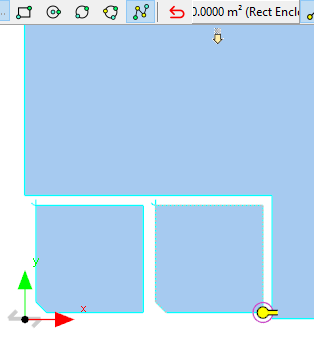
4.The shape is removed.
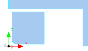
5.Repeat for the other shape also, until the final result is achieved:
6.The leads remain, but these do not matter.
7.Finally Click Edit Plate again to commit the changes and to exit Plate Editing mode.