Parts and plates now have a grain angle property, and parts have a property to enforce grain constraint. Grain constraint is used to make parts align with a plate direction, reducing the number of rotations allowable. It can be for reasons of part structural strength (steel plate often has better mechanical properties along its long axis due to the rolling process) or to reduce chances of parts tipping during cutting (eg nesting long skinny parts across slats rather than along them).
As Grain Angle is stored with plates and parts, so it is transformed when the plates and parts are transformed, for example if an offcut remnant is rotated 90 degree to improve nesting, so is its grain angle.
It affects both autonesting and manual nesting, though grain constraint can be overridden when manually rotating parts if the Alt key is depressed.
Setting Plate Grain
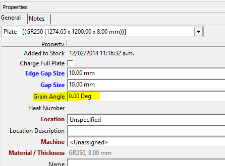
Plate grain is set as a property on plates, via the Grain Angle, being defined as “the angle the grain line makes with the x axis”. This is allowed to be set in the range 0 degrees up to, but not including, 180 degrees. Note that grain direction defines an infinite line rather than a true direction, as such rotating grain direction by 180 degrees has no effect.
Normally plate grain is aligned with the long axis of the plate, and normally in Primecut we load plates with their grain angle by default set to zero, hence aligned with the long edge of the plate.
This can be changed on a plate by plate basis via the grain angle property:
Further, a default can be set for new plates created via user settings (Tools, Options, Settings) and the Default Plate Grain Angle setting. Note these settings are per user (at this time) so care must be taken to ensure all users set this up in a similar manner. typically this will be 0 or 90 degrees, it would be very unusual for it to be set to anything else.
Note the setting here also for Grain Constraint Tolerance, this is used when manual nesting to allow parts to be tipped within plus or minus some angle of the grain alignment.
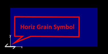
In Nesting mode the plain grain symbol is shown overlaying the plate origin as follows, in this case grain is horizontal, ie plate grain angle is the recommended default 0 degrees:
If a plate is transformed (eg an offcut is rotated 90 degrees) the plate’s grain angle is automatically transformed as well, so plate grain can be preserved from parent plate through to offcuts.
Setting Part Grain
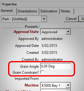
Parts have both a Grain Angle property AND a Grain Constrain property, and these are stored against each part revision. Creating a new part revision inherits its parent revisions grain settings of course.
If Grain Constrain is not checked then the Grain Angle has no effect, and the part is free to nest in any orientation .
When clustering parts in nesting mode, grain is preserved where possible, ie if any parts in a cluster have grain constrain enforced then the cluster will also have its grain enforced and will use the orientation of the parts within the cluster and their grain angle to set the cluster’s grain angle. NOTE: If parts are manually nested and rotated so that grain alignment is broken, then clustering them may cause unexpected results in terms of the cluster’s resulting grain angle.
When loading parts into a workorder a shortcut means of setting grain has been provided on the Load Part dialog. This has a number of options detailed as follows:
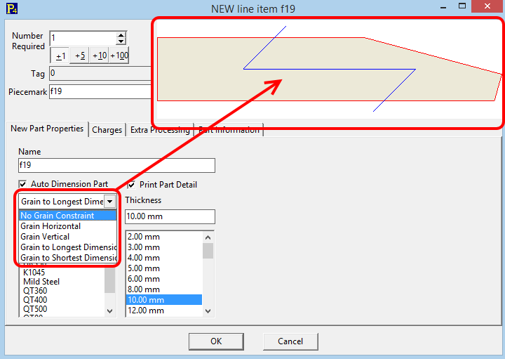
•No Grain Constraint: Straightforward, Grain constrain is unchecked on the loaded part
•Grain Horizontal: Grain is constrained and the part’s Grain Angle is set to 0 degrees.
•Grain Vertical: Grain is constrained and the part’s Grain Angle is set to 90 degrees.
•Grain to Longest Dim: The part is reoriented to a horizontal layout, grain is constrained and the part’s Grain Angle is set to 0 degrees.
•Grain to Shortest Dim: The part is reoriented to a vertical layout, grain is constrained and the part’s Grain Angle is set to 0 degrees.
From the above you can see that all graining options but Grain Vertical set the part’s Grain Angle to 0 degrees. This is preferable to 90 degrees as it means parts typically nest as they are displayed on a plate that also has a 0 degree grain angle.
Like material and thickness this setting is remembered between parts to speed up data entry.
Automatic Part Grain Recognition from Grain Marks in Drawing
Grain can also be automatically recognized on a part, if eitther of the following geomtric features are identified:
•If a TEXT entity is found in the DXF or DWG containing the work “GRAIN” or “Grain” (a case-insensitive comparison is made) and nothing else, then the part will be rotated on import so that that text is horizontal and Grain will be enforced with a Grain Angle of 0 degrees. ie the angle of the word “grain” determines the grain angle.
•If a grain symbol similar to below is identified within the drawing, then the part will be rotated on import so that that the grain symbol is horizontal and Grain will be enforced with a Grain Angle of 0 degrees.
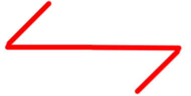
•A grain symbol is defined by:
•An open path composed of 3 lines
•The end two segments of which must be the same length and longer than the longer middle segment
•The end segments must make equal and opposite acute angle with the middle segment
If loading a part and a grain mark is recognized, the grain setting dropdown is overriden and hidden.
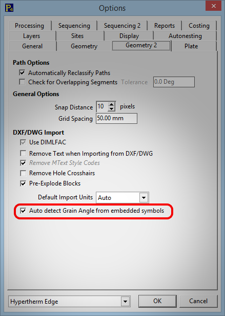
Automatic part grain detection can be enabled or disabled through user options: Tools menu, User Options, Geometry 2 tab:
Nesting parts with grain
As already noted autonesting will nest grain constrained parts so that their grain angle coincides exactly with the plate’s. For example if both plate and part grain angles are 0 degrees (horizontal grain, typical case) then the allowable autonesting orientations are just 0 and 180 degrees. Autoclustering will also produce grain constrained clusters.
When manual nesting, you may rotate the part using the rotation handle to to any angle within the Grain Constraint Tolerance setting (see earlier) and it will then “stick”. Trying to rotate beyond the stick point will eventually snap to within tolerance of the 180 degree alternate grain alignment.
Forcing Grain Alignment Out Of Tolerance
You can force it to any angle, including those outside the Grain Constraint Tolerance by holding down the Alt key as you drag the handle, or by pressing Alt- and [ or ] which will rotate in 5 degree increments from the base grain alignment angle. Any parts which have been forced out of grain alignment tolerance will have a red grain mark on them to show that this is the case.
Restoring Parts Into Grain Alignment
To quickly restore a part which is not exactly grain aligned, wherther within the tolerance or outside of it, to be exactly grain aligned click [ or ]- these keys which normally rotate the part in 90 degree increments will now snap between the two exactly grain aligned orientations, 180 degrees apart.
Grain display in nesting
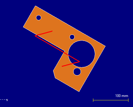
Grain constrained parts nested within tolerance of their grain angle look no different to normal parts in the nest. However if a grain constrained part is nested so that its grain is outside tolerance it will be displayed with a large red grain symbol on it showing the parts grain direction (plate grain direstion is indicate atthe plate origin):
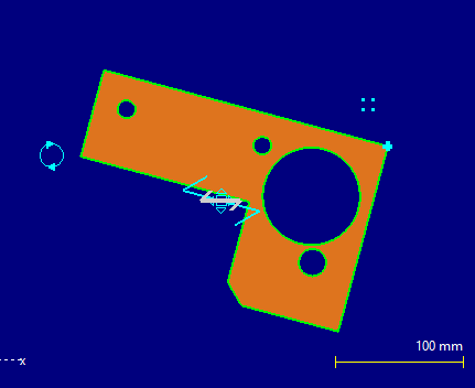
If the part is selected then we can see some extra information. If the part exactly matches the plate grain angle then a single grain symbol will be shown on the part:
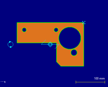
If the part is nested at a slight angle to the plate grain, but within tolerance then a second plate grain symbol is also drawn on the part when it is selected:
Reporting On Part Grain Is Not Supported
At this time the grain property is embedded in the part xml data and not available through simple SQL queries, so not available to the reporting engine.