Corner loops are most often used when cutting with a bevel, but might also be used with aluminium. This is because the arc lags behind significantly on this material, and when cutting thick plate the corners may be rounded at the underside of the plate. Using a corner loop eliminates this rounding.
This part (hypothetically) requires a high degree of consistency and for this reason we are processing the part on its own before nesting. By doing this we ensure that all of the nested parts will have the same characteristics, and the nest spacing will take into account the decorations (leadins and corner loops) that we have placed on the part. Certainly if corner loops are to be used on a part, it is advisable to apply processing to the part rather than the nested plate. We are also drilling and tapping the part in order to illustrate how these tasks are performed.
1Open the Workorders mode.
2Under Invoice Number search for Mixed Processing, making sure all other fields are all inclusive. Click Refresh.
3Double-click on the Mixed Processing workorder.
4Double-click on the Mixed Part 2 part in our parts explorer. A warning will appear that there is a newer revision of the part. Usually you want to start from the most up to date version when editing a part, but in this case will just click Yes to dismiss the warning.
It has been determined that all corners, with the exception of the two at the top, are critical. Consequently we want the cut to start at one of these top corners, and need to create corner loops on all of the other corners. Most of this can be achieved by selecting the right settings in the processing options dialog, the only intervention required will be the removal of one corner loop.
5Click on the Processing editor tab and Click on the Process All button. When the dialog appears press the ![]() button for the Closed Paths, External and Crops field. Note the colored connecting line between the processes on the left are all the fields that share the current advanced options page.
button for the Closed Paths, External and Crops field. Note the colored connecting line between the processes on the left are all the fields that share the current advanced options page.
Select the settings shown below (at left).
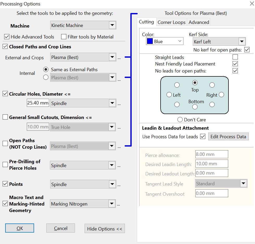
6In the middle of the tool options Cutting tab is the Leadin & Leadout Attachment selector. Click on the Top radio button. This will direct PrimeCut to place the start of the cut at this location.
Be aware that this does not dictate absolutely where PrimeCut will place the leadin and leadout. PrimeCut will take your selection into account, but if it can find a more 'sensible' location that will be used instead. In such cases the leadin can be placed manually.
7Still in the processing options dialog, Click on the Corner Loops tab. This gives us further processing options.
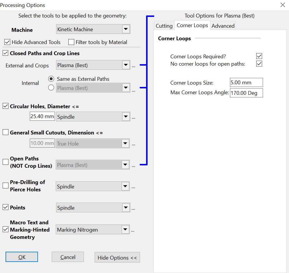
8Match your processing options to those shown above. Especially check the Corner Loops Required? checkbox.
9Now Click on the ... button ![]() under Circular Holes up to Diameter in order to display the relevant Tool Options.
under Circular Holes up to Diameter in order to display the relevant Tool Options.
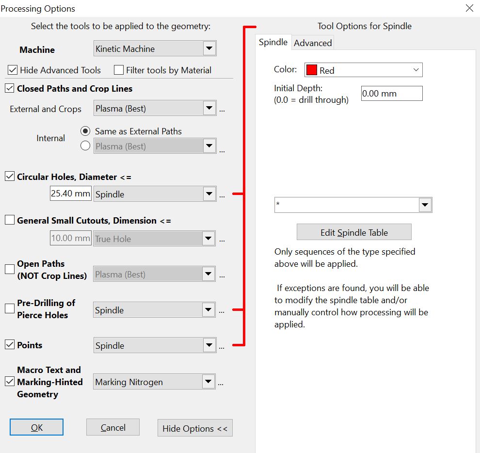
▪The Initial Depth setting controls how deep the hole will be, but 0.00 is an exception that PrimeCut takes to mean through the plate. If you want to drill only to a certain depth, then you enter the desired value as the Initial Depth. In this case leave the value as 0.0.
▪From the dropdown box we can see all the tooling combinations we have stored as options for processing with the spindle. Select '*', since we don't want to process all the holes in the same way.
10Press the Edit Spindle Table button.
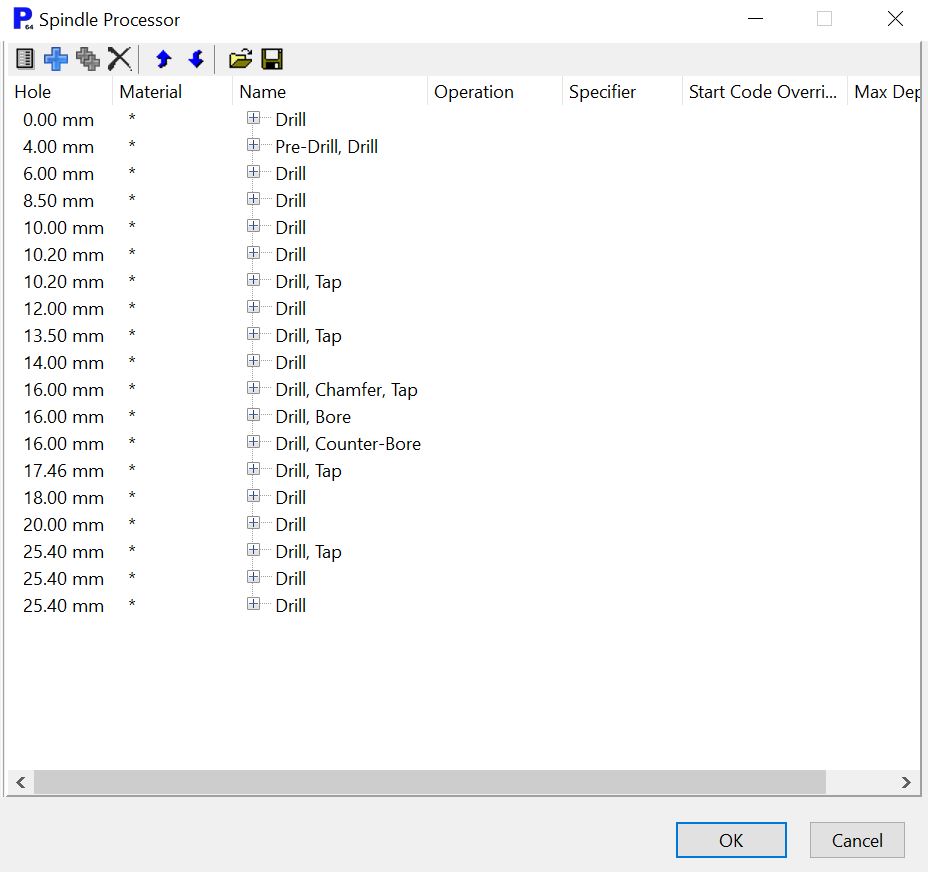
These are the spindle tooling parameters currently loaded into our postprocessor file.
The Columns are used as follows.
▪The Hole column gives the size of holes that we have tooling loaded for.
▪The Material column specifies which material the tool can be used on. If it is marked with an asterisk (*), then that tool can be used on any material.
▪The Name column is the name of the whole process, as it appears in the dropdown box we opened in the previous step.
▪The Operation column is the name of that operation within the process.
▪The Specifier column gives the tool name that will be inserted into the NC code, and which the machine will then attempt to select. This is why the tool names must match between PrimeCut and the machine.
▪The Start Code Override column gives the NC code that replaces the default NC code (usually M30 D{depth}) for that tool. This is used for custom start processes, for example when the tool isn't simply moving up and down on the plate (some chamfers, True Hole). When this field is empty, the default start code is used.
The buttons at the top of the window
▪![]() Edit, to edit the selected Sequence or Operation.
Edit, to edit the selected Sequence or Operation.
▪![]() Add Sequence, to add a new sequence to the table.
Add Sequence, to add a new sequence to the table.
▪![]() Add Operation to add an operation to the selected sequence
Add Operation to add an operation to the selected sequence
▪![]() Delete, to delete the selected Sequence or Operation
Delete, to delete the selected Sequence or Operation
▪![]()
![]() Move Up and Move Down, to change the position in the order of operations in a sequence the selected operation is performed.
Move Up and Move Down, to change the position in the order of operations in a sequence the selected operation is performed.
▪![]() Open from file, to open a table of spindle sequences from a file.
Open from file, to open a table of spindle sequences from a file.
▪![]() Save to file, to save the table of spindle sequences to a file.
Save to file, to save the table of spindle sequences to a file.
Our part has two 25.4mm (1") holes and one 20mm (0.7874") hole. The larger holes are to be drilled only, and the smaller holes are to be drilled and tapped. We will add a new entry for 20mm, with a new Drill and Tap specification in order to illustrate how to use the table.
The name you use to describe the drill is critical because this is included in the NC program and instructs the controller on which bit to select. Consequently the name being used here must match exactly what is used on the controller, otherwise there will be an error and the program will not run.
11Click on the Add Sequence ![]() button, to add a sequence to the table.
button, to add a sequence to the table.
Enter the following details in the dialog, to add the first process in a new sequence. Click OK.
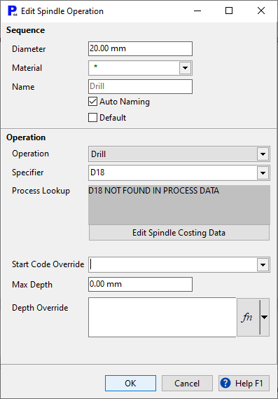
12Click Add Operation ![]() to add an operation to the current sequence. Under Operation, in the Operation field select Tap. Under the Specifier field type T20. Click OK.
to add an operation to the current sequence. Under Operation, in the Operation field select Tap. Under the Specifier field type T20. Click OK.
13Click OK to close the spindle table.
14Click OK to process geometry.
15The following dialog should open, because we did not specify what tools to process the holes with, and we have more than 1 tool for these hole sizes.
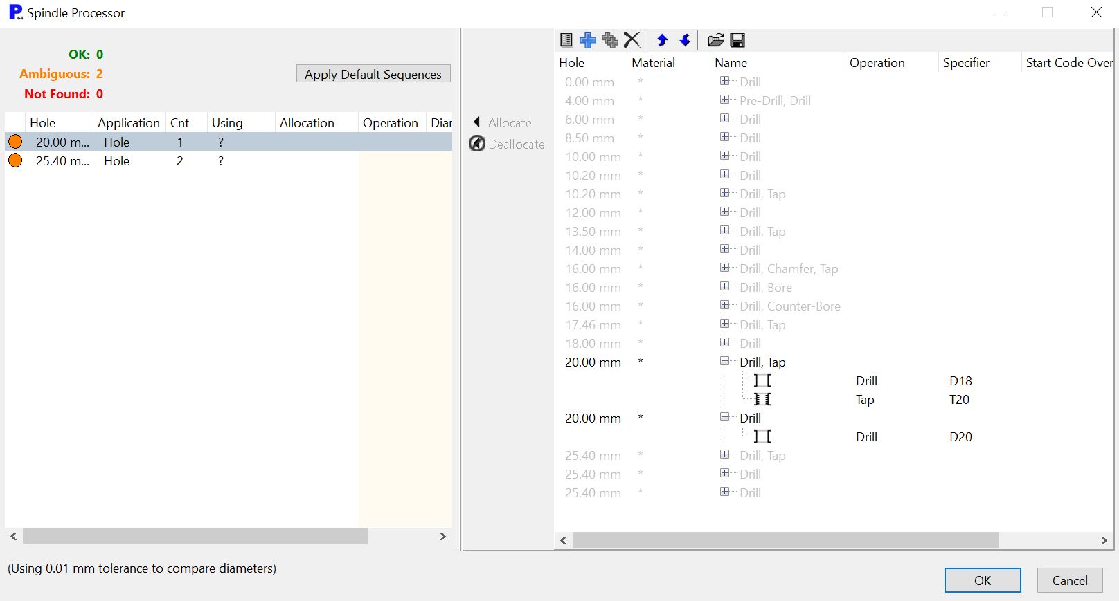
16For the 20mm hole, select the 20.0mm Drill, Tap option. Right click and Click the < Allocate button. Similarly select the first of the two Drill options for the 25.4mm Drill. Click the < Allocate button. Click OK.
You can see that all of the holes are being drilled, and the partial circle around the smaller hole indicates that it is being tapped also. To make changes to the specified tooling after a part has been processed you can select it and then view and change the properties.
Since the top corners are not crucial we now want to remove the corner loop at the top right corner of the part. This is simply a matter of selecting and deleting it.
17Zoom in on the top of the part and select the corner loop. A crossing rectangle (from right to left) that just touches the path of the corner loop is the easiest way to do this.

18To delete this corner loop simply press the Delete button on your keyboard.
In some situations you may wish to re-create corner loops. In this case you should select the path to view its properties, then untick the Corner Loops checkbox and Apply, retick it and Apply again.
Close the mode and Click Yes to save when prompted.