If material usage is of greater importance than part consistency, then it is likely that processing will be applied after parts are nested on the plate. In doing so you are able to pack the parts more tightly because their placement is not influenced by decorations (such as leadins and corner loops).
When processing is applied to the plate these decorations will need to be accommodated, and a knowledge of the issues involved can help to ensure that this is executed smoothly. In this example we will deliberately generate problems in order to illustrate these issues.
1Open the Nesting mode from the start screen.
2Click Open Parts ![]() .
.
3Under the Invoice Number search criteria, search for Processing: Leadin Placement. Change the dropdowns to "All Cut By Dates" and "Show All" if nothing appears. Only the Leadin Rectangle part should appear in the list. Double-click on it.
4Click the Open Plate ![]() button. Select New Plate
button. Select New Plate ![]() . Enter the following details and Click Add to Stock and Close
. Enter the following details and Click Add to Stock and Close
Width: |
800mm / 31.50" |
Length: |
1000mm / 39.37" |
Plate Material: |
GR250(A36), 20.00mm |
Gap: |
7mm / 0.2756" |
5Double-click on the plate in the explorer to open it.
6Drop the Rectangle part onto the plate.
7Create a 6x12 array in the bottom left corner, filling the plate.
8Click on the Processing tab to open the processing editor
9Click Process All.
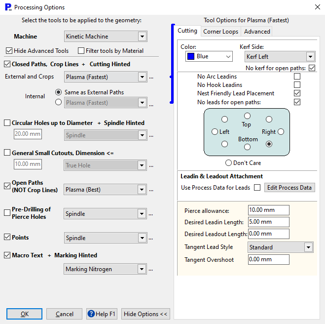
10Click the ... button ![]() to the right of the External field in Closed Paths. Uncheck Use Process Data for Leads, set the Pierce allowance to 10.00 mm, and set Leadout Length to 0. The dialog should look as shown: if not set it as shown.
to the right of the External field in Closed Paths. Uncheck Use Process Data for Leads, set the Pierce allowance to 10.00 mm, and set Leadout Length to 0. The dialog should look as shown: if not set it as shown.
11Click OK to apply the processing. The following warning message will be displayed:
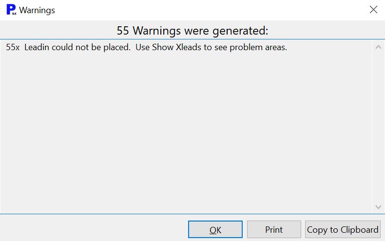
This warning was generated because PrimeCut has tried to create leadins based on the tool settings, but the small plate gap (7mm) has caused a conflict.
12Click OK to close the warning dialog.
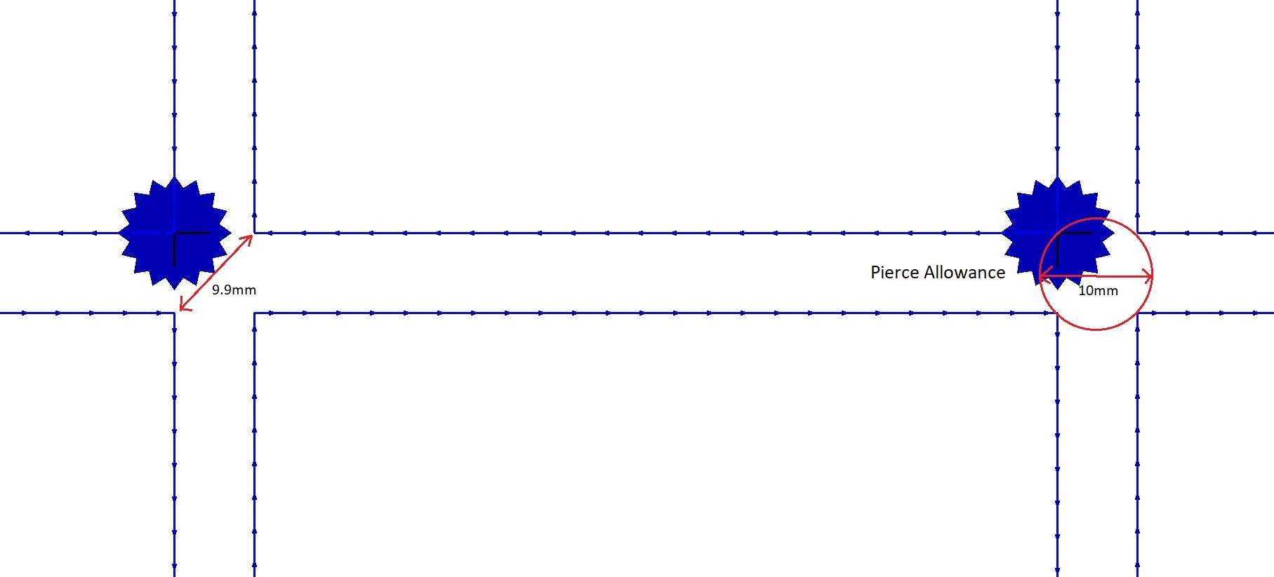
The setting that led to the warning was the Pierce Allowance (diameter), which is used to create a circle around the piercing point. If any parts conflict with this circle it is an indication that they will be adversely affected by the piercing process, and therefore the leadin cannot be placed at that point. The 7mm (0.2756") gap setting of our plate means that corner to corner the gap between parts is 9.9mm, and the pierce allowance for the '200A 02 N2 (GR250(A36))' tool is 10mm (or 0.392"). This is illustrated in the figure below.
13Click on the Show XLeads ![]() button in the processing editor to view the leads that could not be placed.
button in the processing editor to view the leads that could not be placed.
The leads that could not be placed are now highlighted in red. This feature is especially useful when dealing with a more complex nest where only a few leads could not be placed. In such a situation you could choose to reapply processing to only those parts.
We will now apply processing again, but will change the pierce allowance so the leads can be placed.
14Click on the Process button. You will see a dialog asking "All geometry has processing. Clear and Reprocess All?". Click Yes on this dialog. The Processing Options dialog will be displayed.
15Again, Click on the ... button ![]() to the right of the External field in Closed Paths in the dialog. Change the pierce allowance down to 9 mm and Desired Leadin Length to 20mm.
to the right of the External field in Closed Paths in the dialog. Change the pierce allowance down to 9 mm and Desired Leadin Length to 20mm.

16Click the OK button to process the plate. This time no warning message has been generated because PrimeCut was able to place all of the leadins.
The last used Pierce Allowance for a tool is the default setting the next time the tool is used.
The small spacing gap has had one other effect. If you zoom in on the lower right of the plate you will be able to see this more clearly.
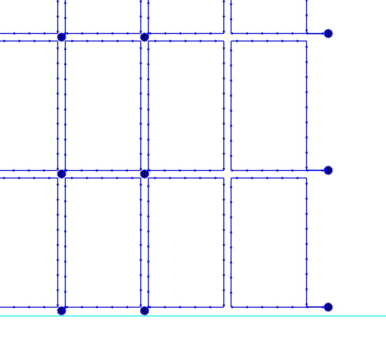
The leadins for the parts at the far right are longer than those of the adjacent parts. On the tool options menu (below 'Pierce Allowance') is a field for 'Desired Leadin Length', which in this case is set to 20mm. The parts on the right have enough space to allow the creation of a 20mm long leadin, but the adjacent parts clearly do not.
PrimeCut handles this situation by shrinking the leadin until it will fit, subject to the pierce allowance remaining clear of other parts. As we saw earlier, if this shrinking results in the pierce allowance coming into contact with other parts the lead will not be placed, and an XLead will be created to indicate this.
17Close the mode without saving