The Roller Sprocket shape is a flat sprocket plate for roller chain: a toothed outside profile sized from the chain's pitch and roller diameter, and a round bore in the centre. The tooth form follows the standard roller chain sprocket tooth form given in Machinery's Handbook (23rd edition, page 2301). The bore can carry one or more keyways so the sprocket can be keyed to a shaft.
It appears in the shapes library under Round Shapes.
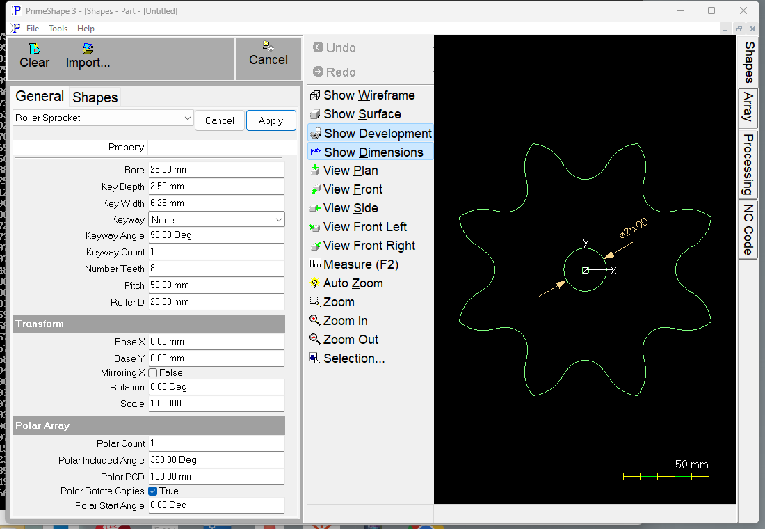
Roller Sprocket in PrimeShape: the property page (left) and the shape with its dimensions (right).
Insert point and direction
The centre of the sprocket (the centre of the bore and of the pitch circle) is the insert point (Base X, Base Y). The roller seats are centred on the pitch circle, whose diameter is Pitch / sin(180° / Number Teeth). The first roller seat is straight up (+Y) from the centre and the others follow clockwise; the toothed outline is one closed path built clockwise.
The bore is a separate profile. Without a keyway it is a plain circle; with a keyway it is one closed path built anticlockwise: out along one wall of each keyway, across its square end, back along the other wall, then round the bore to the next keyway.
The Bore dimension is drawn across the bore. With a keyway, Key Width is dimensioned across the end of the first keyway and Key Depth along its centre line. The teeth have no dimensions.
Properties
Property |
Description |
Default |
Bore |
Diameter of the centre hole (mm or inch). Without a keyway, a Bore of 0 gives a single point at the centre instead of a hole. The Bore is not checked against the teeth in that case, so make sure it is smaller than the root of the teeth. |
25 mm (1 in when working in inches) |
Roller D |
Roller diameter of the chain (mm or inch). The roller seats are cut slightly larger than this: seat radius = (1.005 x Roller D + 0.003 in) / 2. |
25 mm (1 in) |
Pitch |
Chain pitch, the distance between neighbouring roller centres (mm or inch). Together with Number Teeth it sets the pitch circle the roller seats sit on. |
50 mm (2 in) |
Number Teeth |
Number of teeth (roller seats) round the sprocket. 5 to 200. |
8 |
Keyway |
Adds keyways cut outward from the bore. None – plain round bore; Custom – Key Width and Key Depth as entered; Metric (DIN 6885) – width and depth taken from DIN 6885-1 for the Bore; Inch (ANSI B17.1) – width from ANSI B17.1 (square key) for the Bore, depth worked out from it. |
None |
Key Width |
Width across the keyway (mm or inch). Used as entered for Custom; for Metric and Inch it is replaced by the standard value when the shape is built. |
6.25 mm (0.25 in) |
Key Depth |
How far the keyway goes beyond the bore, measured on the keyway centre line from the bore to the end of the keyway (mm or inch) – the hub depth t2 of DIN 6885, so the hub measures Bore + Key Depth. Used as entered for Custom; replaced by the standard value for Metric and Inch. |
2.5 mm (0.1 in) |
Keyway Angle |
Direction of the first keyway centre line, anticlockwise from +X (degrees). |
90° (straight up) |
Keyway Count |
Number of keyways, spaced evenly round the bore starting at Keyway Angle. Minimum 1; a value above 1000 is refused when the shape is built. |
1 |
Key Width, Key Depth, Keyway Angle and Keyway Count have no effect while Keyway is None. Sprockets saved before the keyway was added open with Keyway set to None and keep their plain bore. The shape does not range-check Bore, Roller D or Pitch itself.
Standard keyways
With Metric (DIN 6885) or Inch (ANSI B17.1) the keyway size is looked up from the Bore each time the shape is built, and written back into Key Width and Key Depth so you can see the values used.
•Metric covers bores over 6 mm up to 500 mm. Both width and depth come from the table.
•Inch covers bores over 5/16 in up to 6 1/2 in. The table gives the key width. The keyseat is half the square key deep at its side walls; Key Depth is that depth on the centre line, i.e. half the key width less the height of the bore arc across the keyway.
A keyway must stay inside the roots of the teeth: its outer corners must be closer to the centre than the bottom of the roller seats (pitch circle radius less the seat radius).
When the shape cannot be built
If the values cannot make a valid shape, the shape is not drawn, a broken-shape marker is shown at the insert point, and the property page shows Warning: Cannot build shape from these parameters. This happens when:
•Number Teeth is less than 5 or more than 200;
•the tooth form cannot be fitted to the Roller D and Pitch – this happens when Roller D is too large for the Pitch;
•with a keyway: the Bore is 0 or less; Keyway is Metric or Inch and the Bore is outside the range of the table; Keyway Count is less than 1 or more than 1000; Key Width is 0 or less, or is not less than the Bore; Key Depth is 0 or less; neighbouring keyways overlap;
•with a keyway, the keyway reaches the roots of the teeth ("Keyway breaks through the outside of the part"), or there is no room for any keyway inside the tooth roots.
If Roller D is 0.357 x Pitch or less (1.4 x Roller D not more than half the Pitch), no teeth are drawn and only the bore is left. No warning is given in this case. Real roller chains have a much larger roller-to-pitch ratio (about 0.6), so this only happens with wrong values.
Every 2D shape also has the Transform properties (Base X, Base Y, Rotation, Scale, Mirroring X) and the Polar Array properties, listed after the shape's own properties.