Sometimes it is desired to embed a command in the machine NC code, for example a change in automatic height control sensing or a change in current.
Primecut allows for tools to have Segment Codes added to them, which can be added to any tool process via the Split/Tag dialog under Code Segments
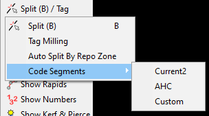
Besides the default 'Custom' code segment which allows for one off insertion of codes, the Machines window allows for code segment types to be added to specific tools.
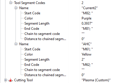
On a tool these settings live under the Mid-Path Codes node, with the tool's named codes under Segment Codes. Each code is a row of its own, captioned with its name and carrying a Remove button, and Add segment code at the end of the list adds another. Segment codes can be placed on both cutting and beveling tool processes.
A code is described by asking whether before what: ticking a box reveals the rows that go with it, so only the settings that apply to this code are on screen.
•Name - The name as it will appear in the Split/Tag menu, and the properties window. Note that a name can be common between two tools, and placing it on a tool process will then look up the start and end codes from that tool processes' tool.
•Start Code - The code to be inserted at the start of the Code Segment. It is possible to use, for example, $PROC_CODE_1$ to refer to the proc code 1 column for the process data that you might select, or any other field macro inside the post processor, it will be resolved in the final code.
•Color - The color it is drawn when added
•Anchor start - Pins the start of the code to a point on the tool path. Ticking it reveals Anchor (Lead in start, Cut path start, Cut path end or Lead out end) and Offset from anchor, a distance measured forward along the path - so a negative offset places the start before its anchor. Left unticked, the start tracks the part geometry as it always did.
•Two ended segment - On for a new code, and what reveals the End Code, Anchor end and Segment Length. Turn it off for a one-ended code: a single code at one point, with no end code, end anchor or length.
•End Code - The code to be inserted at the end of the Code Segment.
•Anchor end - As Anchor start, for the other end. With both ends pinned the coded length follows from the two anchors, so Segment Length is not asked for.
•Segment Length - The initial segment length when placed, used when only one end is anchored, or neither. (Can be edited once placed on the cut plan with handles and the properties window)
•Place Automatically - The initial state of this code's tick box on each new cutting or beveling process. Only a code with an anchor gets a tick box - see Choosing which cuts carry a code below.
•Chaining - A sub-node holding Chain to segment code and Distance to chained segment. Sometimes you want more than a start and end code, e.g. you are ramping current or speed up or down in stages. Naming another code adds it that distance after this one. Naming this code repeats it along the path until the path runs out. A code that carries an anchor of its own cannot be chained to, because that anchor is what places it, and a member that will not fit ends the chain rather than being stacked on the one before it.
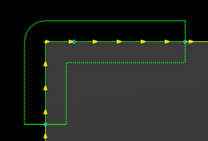
A code segment in the wild
Coded segments appear as a change in color of the cut path, with a dotted outline as shown (the color depends on the color chosen for the segment). The arrows however remain the color of the cut path. There are 3 handles on the code segment. The middle handle moves the segment without resizing and the end handles move the start and end of the segment, resizing the cut. A code that is not anchored cannot be moved onto lead ins or lead outs (a corner loop can occur in the middle of a code segment without issue). An anchored code is measured along the whole tool path and so may sit inside a lead - measuring from Lead in start counts the travel since the arc was struck, which is how a code can fire part way along the lead in. Note that dragging a start past the end will push the end point.
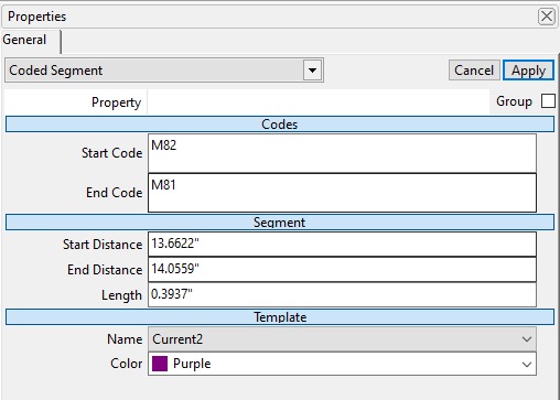
Code Segment Properties
The properties window of a code segment allows for editing of the Start and End codes, however, if they are changed, then they are renamed the keyword 'Custom' to indicate that they are non standard for the name they were originally given.
Choosing a different type of code segment under Name will change the Start and End codes to match the new name.
Anchor start and Anchor end pin either end of a placed code to a point on the tool path, with a Start offset and End offset from it. An anchored end keeps its distance from that point as the part is resized, the leads change, or the code is mirrored.
Start Distance is the absolute distance from the start of the code segment along the cutting process (after the leadin), and End Distance likewise to its end. These are offered while the code tracks the geometry - an anchored end is described by its anchor and offset instead.
Length is the absolute distance between the start and end of the code segment. With both ends anchored the two anchors decide it.
A code too long for the cut it is on is shortened to fit rather than dropped, and re-expands if the part grows - the distance the post asked for is kept.
Choosing which cuts carry a code
A code that carries an anchor does not have to be dropped by hand on every cut. Set Place Automatically on it and Primecut puts it on each new cutting or beveling process of that tool, pinned where its anchors say.
Every anchored code of the process's tool also appears as a tick box in a Mid-Path Codes group in the process properties, so the operator decides which cuts carry it - tick to put it on this cut, untick to take it off. Place Automatically only decides how that box starts out on a new process.
Placement happens once, when the process gets its tool, and the placed code owns its position from then on. Editing the tool afterwards does not reach back into processes that already exist, and a code the tool no longer names keeps the codes and anchors it was placed with, carrying on as Custom - changing a machine's post never removes what is already on a nest.
Voltage latching
Voltage Latching is a ready made segment code that lets a plasma cut measure its own arc voltage instead of following the voltage set for the process. It is offered by Add segment code, and can be offered to every tool on a machine at once from the Machines window.
See Voltage Latching.
Automatic Cut Overlap Detection
As well as placing codes by hand, a tool can automatically mark where the current cut crosses a cut that was sequenced earlier - for example where a later cut runs back over material an earlier cut has already been through. This is enabled per tool with the Detect Cut Overlaps tick under Mid-Path Codes, which reveals the settings below. The detection is relatively expensive, so it is off by default; turn it on only for the tools that need it.
Each detected overlap is marked with the tool's own overlap code (unlike a manual segment code, it is not looked up by name):
•Start Code - the code inserted where the overlap begins.
•End Code - the code inserted where the overlap ends.
•Color - the colour the overlap marker is drawn.
•Start Offset / End Offset - a signed distance (mm) that extends (positive) or shrinks (negative) the detected overlap before the start and end codes are placed.
Crossing depth macros
Two cuts cross at some depth through the plate, and both the Start Code and the End Code can read that depth. Four values are supplied as positional %s parameters (the same placeholder mechanism used elsewhere in the post processor), each a percentage where 0 is the top surface and 100 is the bottom:
•%0:s - start depth (the crossing depth at the start of the overlap)
•%1:s - end depth (the crossing depth at the end of the overlap)
•%2:s - minimum depth (the shallowest crossing depth over the overlap)
•%3:s - maximum depth (the deepest crossing depth over the overlap)
Both codes receive the same four values. For example, a Start Code of ; overlap starts (startDepth:%0:s, endDepth:%1:s, minDepth:%2:s, maxDepth:%3:s); and a matching End Code will each report the full set at their respective ends of the overlap.