Some posts require special processing to provide machine-specific functionality.
Substitutes feed word into the program, using a material lookup feedrate for the current cutting/marking/beveling process, converted into the current code units (mm/min or ipm) and scaled by the Speed Scale Factor. See Machine Feed Settings
Similar to $FEED_STD$ above but used on bevel tools, it instead uses the bevel angle adjusted speed. Each Bevel tool has its own setting to select a Bevel Feedrate Multiplier Type (Currently two models are supported Generic for older plasmas, and HPR for HPR and XPR style High definition plasma). See Time Estimation: Bevel
$KERF_MODE:<mode>[:<int/ext>]$
Writes a kerf word. Requires a parameter<mode> which can be one of the following:
| NONE | Inserts a Kerf None Code, Typically G40 |
| LEFT | Inserts a Kerf Left Code, Typically G41 |
| RIGHT | Inserts a Kerf Right Code, Typically G42 |
| RESTORE | Inserts a Kerf Code for the mode expected by the program. |
Also can take and additional parameter of INT or EXT to specify an internal or external kerf type.
eg
$KERF_MODE:LEFT:INT$ sets a left internal kerf
Also can take an additional parameter of FORCE_ADD to always add the kerf code even if it is unchanged, as required for some post processors.
eg
$KERF_MODE:NONE:FORCE_ADD$ always adds a kerf none, even if a kerf none was used previously
see Pierce Method
$PROC_CODE_OF_FIRST_PROC_IN_SET:<Process IDs>:<Process Code Num>$
e.g. $PROC_CODE_OF_FIRST_PROC_IN_SET:5100,5101:1$ Looks through the sequence for the first process with Process ID 5100 or 5101, and returns the $PROC_CODE_1$ value for that process, (The proc code number is the one given after the last ':'). If no process can be found then the default process for the first process ID in the set is used. If nothing is returned, there may not be process data for that processID for the chosen material thickness.
$CODE_NAMED:<Process Code Name>$
Returns the first ProcCode or AuxCode of the given name. e.g. $CODE_NAMED:Gas$ returns the value of first Proc_Code or Aux_Code with a name matching 'Gas'
$CODE_NAMED_OF_FIRST_IN_SET:<Process IDs>:<Process Code Name>$
e.g. $PROC_CODE_OF_FIRST_PROC_IN_SET:5100,5101:Gas$ Looks through the sequence for the first process with Process ID 5100 or 5101, and returns the value of first Proc_Code or Aux_Code with a name matching 'Gas'
This is substituted for by the active tools internal or external kerf indicator. The default for these (for historical reasons) is D21 and D22, but they can be replaced on the tool to be anything, eg INNER_CONTOUR, STANDARD_CONTOUR etc.
$PLATE_HEAT$ , $PLATE_SERIAL$, $PLATE_TESTCERT$
Plate heat and serial number and test certificate reference. See Label Parts.
Inserts program parameter. These are set under plate properties, and configured in the machines section.
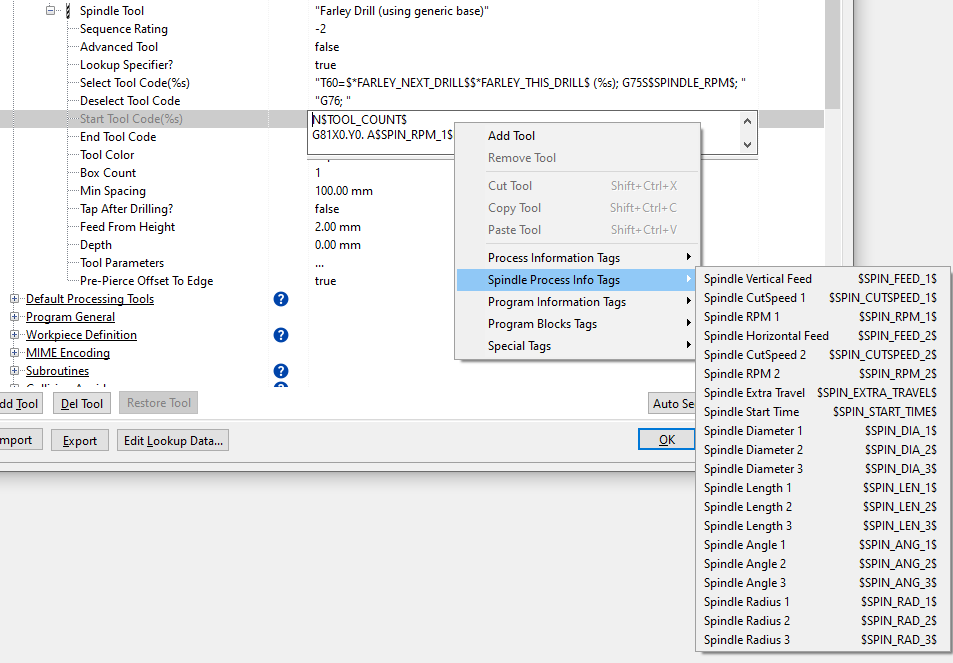
Used to insert the spindle speed in RPM, eg for some Farley controllers we might use:
G75S$SPINDLE_RPM_1$
Diameter of the current tool in active units (mm or inches)
Feed per revolution of the selected spindle tool in active units (mm or inches)
Nett Feedrate in mm/min or ipm of the current tool.
Peck Parameters for the current spindle tool, SPINDLE_PECK is the peck depth increment, SPINDLE_PECK_TYPE is usually encoded as an integer.
Effective tip Depth of the spindle process in active units (mm or inches) (equal to the depth, or if drilling through the plate, the plate local thickness + overshoot)
This will substitute either the Internal Path Marker or the External Path Marker codes depending on whether a path is internal or external; open paths will get the External Path Marker.
The current tool process number (numbering is defined in the post by ToolCount Start Number and Tool Count Number Increment under Program General
see also $RAPID_NUM$
The total number of processes in the program (or in the current subroutine).
The current rapid number. Rapid numbers are defined in the post by Rapid Start Number and Rapid Number Increment under Rapids.
Very similar to $TOOL_COUNT$ above, but in some applications rapids may increment more frequently. Using both also allows two different numbering schemes.
Control Logic Macros
Once any internal codes have been resolved to numeric values, this evaluates the formula to a number.
Also handles inequality signs, in which case true is returned as 1 and false returned as zero.
E.g. {10 > 5} will resolve to 1
When followed by a carriage return, this symbol gets removed along with the carriage return, to increase legibility
$SET:...$...$ENDSET$ or $SET$...$VALUE$...$ENDSET$
There are two syntaxes available for setting a "variable". The first and simpler syntax is:
$SET:<name>$<value>$ENDSET$
This assigns <value> to the variable <name>.
Variable names are arbitrary strings, and the variable are global.
They are string variables, however their string content can represent numbers when needed.
E.g. $SET:SelectedCarriages$2$ENDSET$ sets the number of selected carriages to 2
If you want to calculate the key string you can with e.g. $SET$XValAtRapid_$RAPID_NUM$$VALUE$$X$$ENDSET$
This can be made more legible in the code with the _ wrap text character
In this example we are assigning the content of the current X position ($X$) into variable ValAtRapid_$RAPID_NUM$
$SET$_
XValAtRapid_$RAPID_NUM$_
$VALUE$_
$X$_
$ENDSET$
Retrieves a value that was save to a string key using $SET above, in any prior code block.
Again, two syntaxes one simple and one where the variable name may be need to be computed:
e.g.
$GET:SelectedCarriages$
or
$GET$XValAtRapid_{$RAPID_NUM$-1}$ENDGET$
The $GETAFTER$ tags are left in the script until after the whole post-processor script has finished, although their string key is processed in the first pass. The values accessed are processed Variables set using $SET further on in the script can then be accessed earlier in the script, accessing variables from the future.
e.g. $GETAFTER$XValAtRapid_{$RAPID_NUM$+1}$ENDGETAFTER$ (will access the X value set in the next rapid, which may only be set later!)
A use case example is in the Penta posts, where we need to count processes (using GET and SET "plus 1"), and insert the process count at the start of the program (using GETAFTER).
The truth statement between $IF$ and $BEGIN$ must either evaluate to 1, which can be achieved by a formula in curly braces {}, or it can be a string comparison using = or <> for equality/inequality (no curly braces), for the text between $BEGIN$ and $END$ be inserted.
To be used carefully -
The truth statement between $WHILE$ and $BEGIN$ must either evaluate to 1, which can be achieved by a formula in curly braces {}, or it can be a string comparison using = or <> for equality/inequality (no curly braces), for the text/code between $BEGIN$ and $END$ be inserted. Make sure that the truth statement depends on getting a variable changed using a set call within the while loop. e.g.
$SET:i$4$ENDSET$_
$WHILE{$GET:i$>0}$BEGIN$_
$NEWLINE$counted $GET:i$_
$SET:i${$GET:i$-1}_
$END$
results in
counted 4
counted 3
counted 2
counted 1
Useful for iterative things like adding multiple carriages to a cut.
$BREAK$ and $CONTINUE$
$BREAK$ breaks out of the while loop without evaluating the next lines, and $CONTINUE$ goes back to the beginning of the loop.
String Parsing Macros
$POS($<string to find>$,$<in string>$)$
Gets a 1-based position of a string in another string, returns 0 if not found
$LEN($<string to measure the length of>$)$
Gets the number of characters in a string
$RIGHT($<string to trim>$,$<# rightmost characters to keep>$)$
Gets the rightmost # characters in a string
$LEFT($<string to trim>$,$<# leftmost characters to keep>$)$
Gets the leftmost # characters in a string
$MID($<string to trim>$,$<from char number>$,$<num of chars to keep>$)$
Gets the middle # characters in a string
$REPLACE($<content>$,$<old string>$,$<new string$)$
Returns a string with all instances of <old string> replaced with <new string>
$SPLIT($<content>$,$<delimiter>$,$<# index of substring>$)$
Returns the #th entry of <content> as delimited by <delimiter>
Custom Machine Macros
Custom machine macros usually begin with "$*"
$*LVD_END_CONTOUR$
This uses LVD documented logic to determine whether to retract the head or keep itr lowered at the end of a cut, it is usually in the LVD Laser End Tool Codes):
BEAM_OFF
$_LVD_END_CONTOUR$
Its output is of the form:
ENDCONTOUR("DOWN", 75.221)
or
ENDCONTOUR("UP", 75.221)
The second numeric parameter is the distance to the next start, and is 0 in the final cut of a subroutine (which always retracts , ie at the end of a part subroutine this will be ENDCONTOUR("UP", 0) )
Typical usage:
engraving =$*LVD_ENGRAVING_LOOKAHEAD$
The Engraving Override Program Parameter (defaults to AUTO DETECT see below) allows you to force the engraving mode:
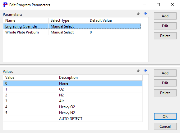
Auto Detect : Looks ahead to find engraving and cutting processes. if no engraving found returns '0' else looks up process code 4 (gas and nozzle) looks at first character assumes O or N and sets it to '1' for O2 cutting or '2' for N2 cutting.
Otherwise if the Engraving Override is set to a non zero value it wll be as follows:
engraving=0 no engraving
engraving=1 O2 engraving
engraving=2 N2 engraving
engraving=3 Air engraving
engraving=4 O2 Heavy engraving
engraving=5 N2 Heavy engraving
These macros are for use in the OAB Bevel system. They allow the initial A and C axis positions for a bevel cut to be accessed as strings.
eg
$*OAB_AWORD$ could be replaced with A45
$*OAB_CWORD$ could be replaced with C90
Inserts a Farley Carousel block, eg :
(CAROUSEL CONFIGURATION)
(STATION 7 DRILL 12Ø)
(STATION 13 DRILL 18Ø)
Deprecated: if no spindle config has been written or the current one does not contain the next drill, the spindle subsystem will write a carousel configuration automatically.
$*FARLEY_NEXT_DRILL$, $*FARLEY_THIS_DRILL$
These reference which Drill is to be used, using the carousel station IDs, packed with a leading zero if necessary. eg, in the tool select:
T60=$*FARLEY_NEXT_DRILL$$*FARLEY_THIS_DRILL$ (%s)
might resolve to (using the carousel example above, station 13 next, station 7 now, using Drill 18):
T60=1307 (Drill 12Ø)
Use with a Farley Fabricator XRP within a spindle with subaxis tool. Outputs spindle XY coordinates in absolute coordinates relative to the spindle clamp position (the origin of the spindle subaxis)
Inserts a list of drills (basically just comments) to suit a Peddinghaus HSFDB machine, eg
;Tooling
#1 1/2
#2 1*1/4
#3 3/4
#4
#5
#6
#7
#8
The first 8 drills are loaded into the toolchanger, tools 9-18 are manually loaded. Only supports a single "carousel" setup at the start of the program.
Selects the current drill number to load for a Peddinghaus HSFDB machine.
For Penta lasers, looks ahead to the start of the next process to write a line like M26 ZX<-10.000> ZY<0.000>
XY2AXISBEVEL
For bevels with two pivot axis aligned with X and Y, whose axis intercept / whose torch tip position from rotation is offset already by the machine, e.g. for a Pentalaser Bevel an XY2AXISBEVEL is appropriate. AXIS 1 is the first axis and AXIS 2 is the second axis in the spherical coordinate system. The first axis direction (X or Y) is set with 'XY 2-Axis Bevel First Axis Direction'
Returns the two axis bevel angles word in the post processor field 'XY 2-Axis Bevel Angles Word' which should refer to $*XY2AXISBEVEL_AXIS_1$ and $*XY2AXISBEVEL_AXIS_1$ in the format expected.
$*XY2AXIS_BEVEL_PIERCE_ANGLES$
Returns the two axis bevel angles word in the post processor field 'XY 2-Axis Bevel Angles Word' which should refer to $*XY2AXISBEVEL_AXIS_1$ and $*XY2AXISBEVEL_AXIS_1$ in the format expected using the pierce angle and rotation of the process not the current position of the torch.
Returns whatever is in 'XY 2-Axis Bevel First Axis Code', with the first axis angle inserted at the %s
Returns whatever is in 'XY 2-Axis Bevel Second Axis Code', with the second axis angle inserted at the %s