Sketch parts are placeholder parts, used when either the exact geometry is as yet unknown, or when quickly estimating from pdfs, sketches or verbal descriptions.
Sketch Parts currently are rectangles, triangles or disks; however cutouts, basic hole patterns and cutouts can be added to represent more complex parts.
Sketch Parts cannot be nested on stock plates, they can however be nested on dummy plates in quoting mode. Primecut will not allow you to schedule a nest containing a Sketch part.
Sketch Parts have their Part Approval Status set to... Sketch. This can be changed to Appoved (or unchecked, or failed) later when the exact geometry is imported into or drawn within Primecut.
Creating a Sketch Part
When you press the Add Sketch Parts icon ![]() the following wizard will appear.
the following wizard will appear.
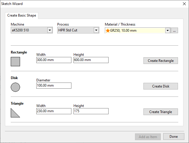
1.Use the drop-down menus to select Machine, Process and Material. These can be changed later if necessary.
2.Choose which shape suits the part you are sketching best and enter in the dimensions. Then click on the Create button for that shape. The add geometry window below should be displayed.
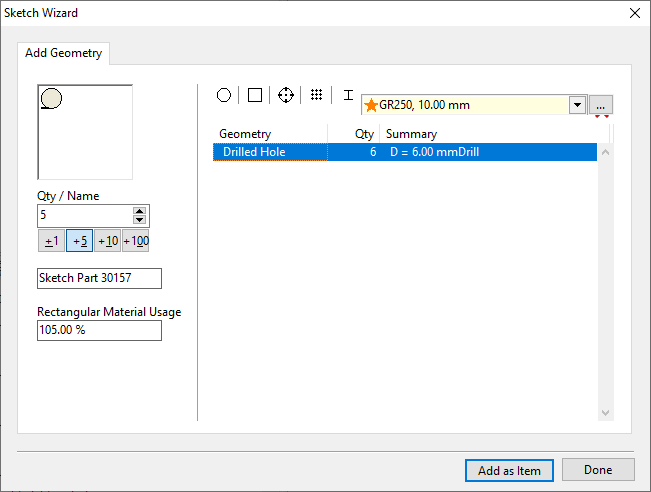
3.Use the Qty/Name section to modify quantity and part name by using the + buttons, the up and down buttons or by entering a value directly.
4.Estimate the amount of material usage as a percent of drawing a rectangle around the extents of the part. Good estimates would be 60% for a triangle, 80% for a circle and 100% for a rectangle.
5.The five icons along the top allow you to add further geometry to the part. The options are circular, rectangular, drilled holes, drilled hole pattern and text. If you click one of these buttons you will see a window similar to the following.
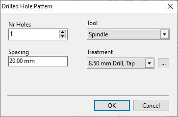
6.Enter in the details of the geometry you wish to add then press OK.
7.Click the Add as Item button on the Add Geometry screen to add the part to the quote/workorder.