PrimeCut can automatically fillet sharp corners as it generates NC code. This feature is a standard requirement for many laser profiling machines.
The fillets are added to the toolpath as the NC code is written, not to the part geometry. Nothing in the nest or the part itself changes, and nothing is filleted until you post.
Tool settings
Filleting settings are a per tool property, under the Corner Filleting group of the cutting tool's settings:
Setting |
Meaning |
Filleting Active |
Master switch. Whether corner filleting will be applied at all to NC output. |
Max Corner Rounding Angle |
Only corners sharper than this are filleted. Default 150 degrees, so a corner that is already a gentle change of direction is left alone. |
Apply to Internal Corners |
Fillet the concave corners — cutouts and internal features. |
Apply to External Corners |
Fillet the convex corners — the outside profile of the part. |
Fillet Radius |
The radius to apply. An explicit number, or a lookup string resolved when the NC code is generated — see below. |
Here for example, only internal corners will be filleted, and the radius used for filleting is looked up from a tool parameter called FilletRadius:
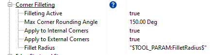
Fillet Radius: an explicit value or a lookup
Fillet Radius is not restricted to a number. It is processed as a postprocessor format string, so the same macros you can use in machine codes are available here and are resolved at the moment the NC code is written. That is what lets a single tool carry the right radius across a whole thickness range instead of needing a separate tool per band.
What you enter |
Resolves to |
1.5 |
A literal radius, in the current display units. This is what most posts use. |
$TOOL_PARAM:<name>$ |
The named tool parameter of the process being cut. The usual choice — the tool parameter is what does the thickness or process code lookup. |
$NEXT_TOOL_PARAM:<name>$ |
The same, but read from the following process. |
$PROGRAM_PARAM:<name>$ |
A program level parameter, the same for every process in the program. |
$PROC_CODE_<n>$ |
Process code n straight from the cut chart for the current material, thickness and tool. |
$LOOKUP:<table>$ |
A value from the named lookup table, keyed on material, thickness and tool. |
$HALF_KERF$ / $FULL_KERF$ |
The kerf for this material, thickness and process — half kerf is the value stored in the database, full kerf is double it. Useful for tying the radius to the tool's own kerf. |
{ … } |
An expression, which may itself contain the macros above — for example {0.5 * $Thickness$}. |
NOTE: Whatever the string resolves to is read as a length in the current display units.
Example: banding the radius by plate thickness
The tool above looks up a tool parameter called FilletRadius. That parameter is set up as an Auto Select (Thickness >=), so the radius follows the plate:
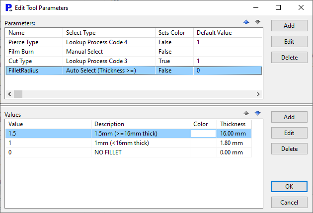
16mm and thicker gets a 1.5mm radius, anything thinner gets 1mm, and the 0 entry turns filleting off altogether. Not automatically applied (there's no 0 thickness material, and cutting processes are not "surface processes"), but having that value there allows the programmer to override it via process properties to "NO FILLET" if required)
NOTE: The sequence the Values are in is important and for a >= Thickness or Area comparison as used here the threshold values should be in descending order as in selecting the value the system takes the first match it finds.
Example: reading the radius from the cut chart
Where the radius is already held as process data there is no need to repeat it in the tool parameter. Setting the parameter's Select Type to Lookup Process Code 3 makes it take its value from Process Code 3 of the cut chart for the current material and thickness:
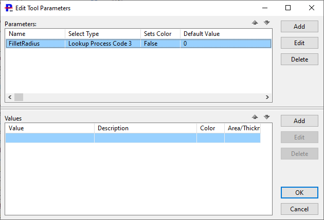
Because a tool parameter is always editable in the process properties after processing, the programmer can still override the looked up radius on an individual process.
NOTE: Tool parameters are looked up and applied as processing is applied. Changes to costing data after processing do not take effect until processing is reapplied.
When the radius cannot be resolved
Corners are only filleted when the resolved radius is greater than zero, so a value of 0 is the normal way to say "no filleting" for a given thickness band.
If the string cannot be resolved at all, PrimeCut does not quietly skip the corners. It writes a warning into the NC code at that point and leaves the path unfilleted:
•Fillet radius resolved blank from '…', no filleting performed! — the lookup ran but produced nothing, usually a tool parameter with no value set for this thickness.
•…: Unable to resolve fillet radius, no filleting performed! — the string could not be resolved, or did not come back as a number. A misspelled parameter name, a macro that is not one of those listed above, or missing process data all land here.
After changing a Fillet Radius, post a test part and search the NC output for these lines. They are the only indication that filleting was configured but did not happen.
Checking the result
The filleting is not visible in the processing window, which keeps showing the sharp corners of the part. Where a tool parameter supplies the radius, that parameter is visible and editable within the process properties.
To confirm the fillets, open the NC preview and zoom in on the corners.
See also Fillet Selection, Tool Parameters, Expressions In Postprocessor Codes and Cooling Points.