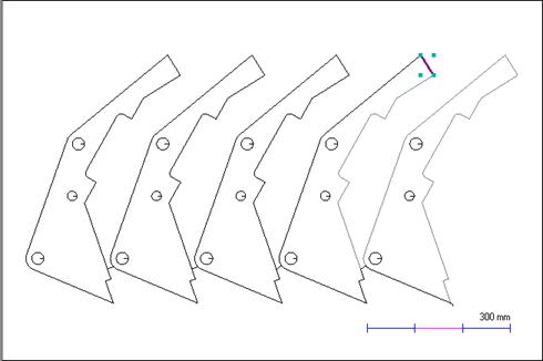
Before applying a new type of bridging, we will need to delete the lines created for the spine bridge. The easiest way to do this is to revert the part back to its original geometry.
1Go to the Geometry editor tab and Click the Revert button.
When asked to confirm, Click Yes.
2Another dialog will appear asking you to select a join tolerance. Enter 0.1mm (this should be the default value), and Click the OK button. Click Close on the warning dialog about it affecting the nest. The part will revert back to its original geometry, and the bridging lines will disappear.
We can now apply auto strike-through bridging.
3As before, use a selection rectangle to select all of the geometry and RIGHT Click to display the popup context menu.
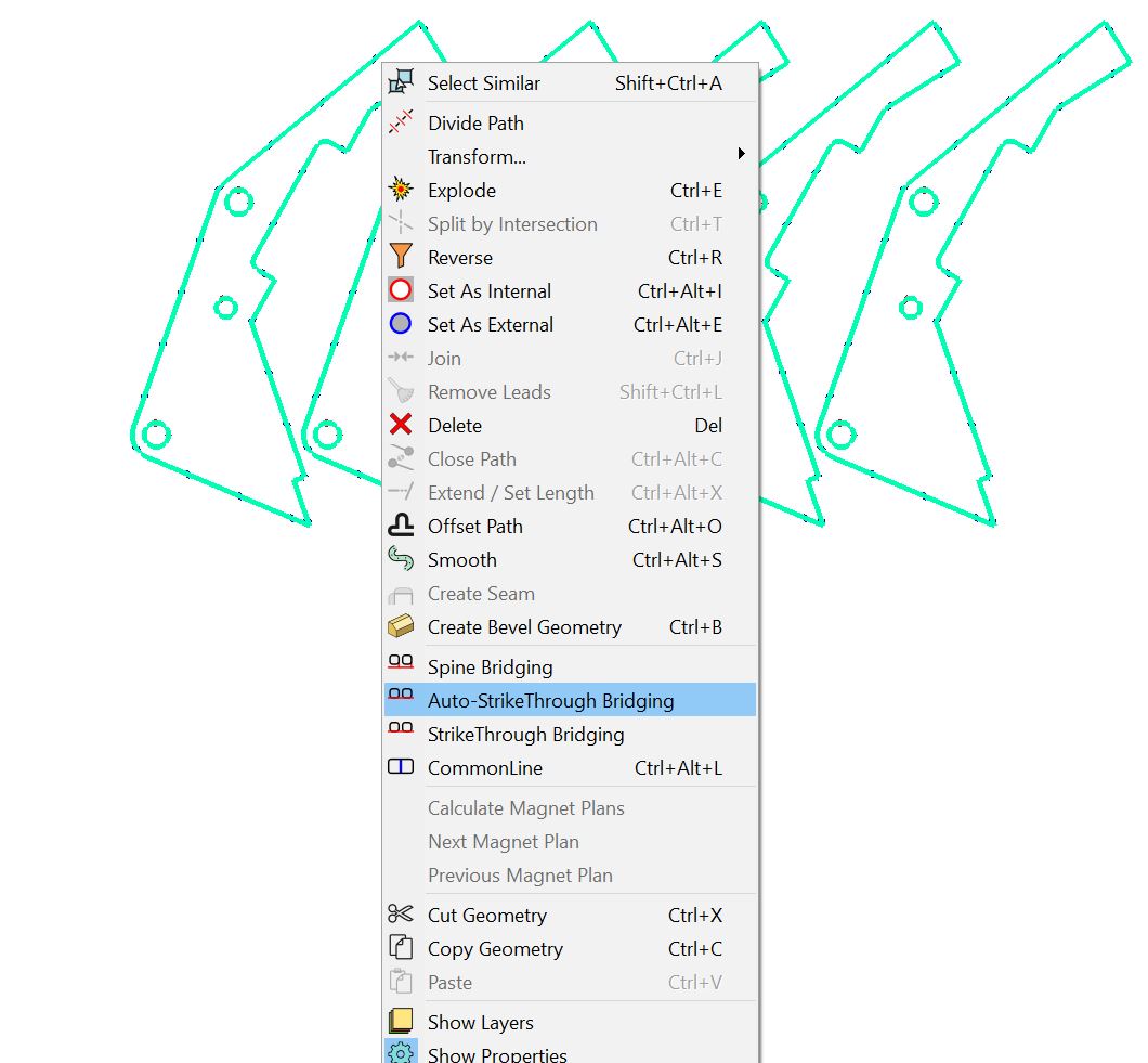
4Select Auto-StrikeThrough Bridging from the menu. Click OK to accept the default 0.00 mm overlap.
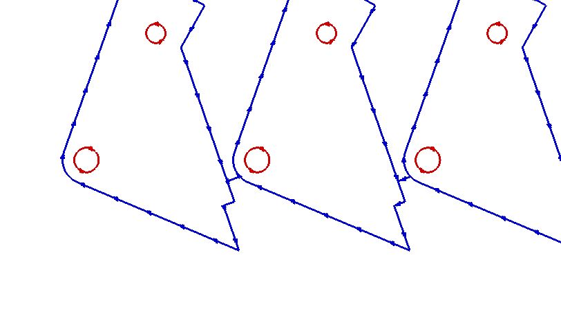
PrimeCut has chosen the shortest path between the parts, and has created the bridge there.
We can now process the part and view its result in the NC Code editor.
5Go to the Processing editor tab and Click the Process All button on the toolbar.
6When the processing options dialog appears, Click the OK button. (As opposed to spine bridging, strike-through does not require any changes to the processing settings.)
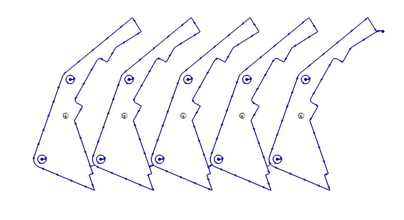
7Go to the Schedule editor tab and tick the Animate checkbox to see a simulation of the cutting process.
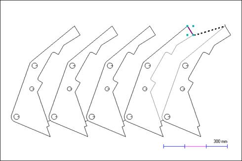
The dotted line in the above illustration has been added to clarify the problem you can have with plate movement. At the moment shown, where we are nearing the end of the cut, all that is holding the two remaining parts is the plate represented by the dotted line. In all likelihood heat deformation will twist the plate below the line and the two parts will end up dimensionally incorrect. By simply moving the position of the leadin (using the technique shown in the spine bridging section) to the bottom right you can remove this problem; see the illustration below.