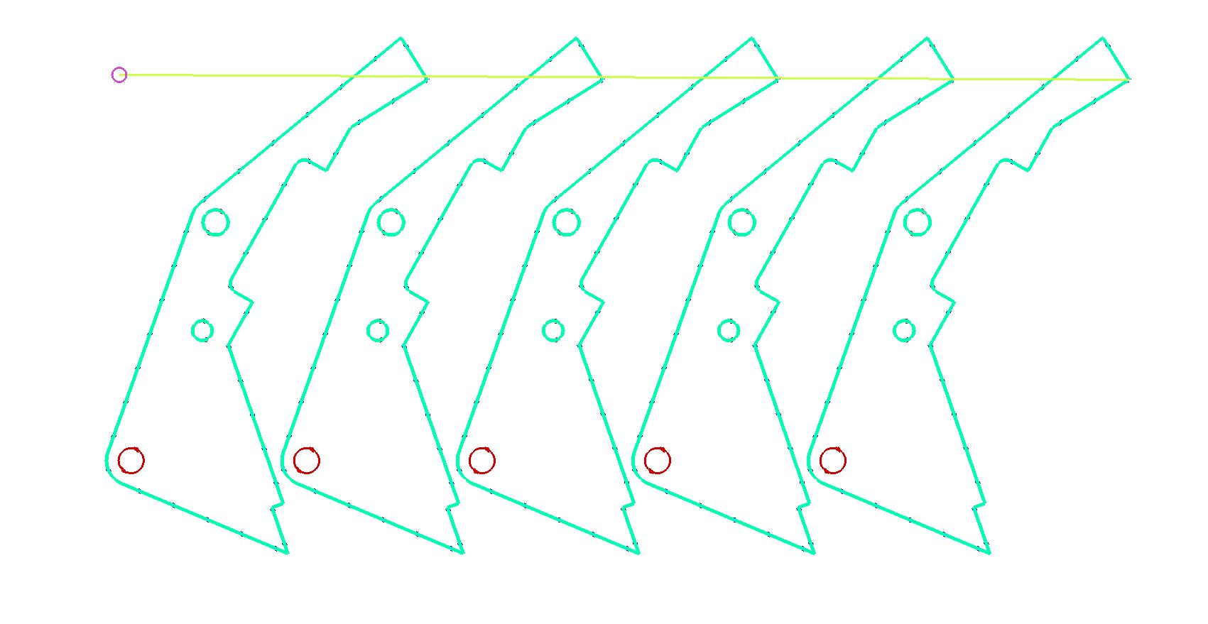
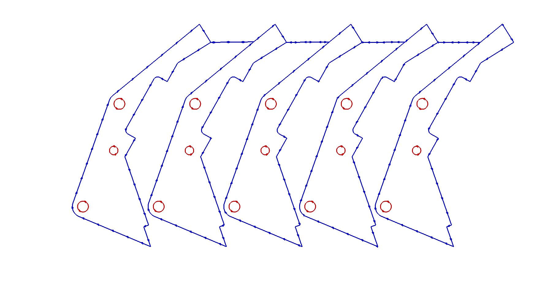
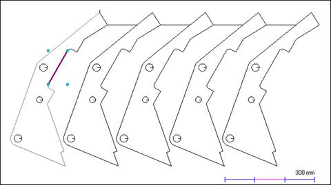
Manual strike-through bridging is much the same as its 'auto' equivalent. The difference here is that you control the line placement instead of PrimeCut. This is useful if the placement of the bridging lines could affect the quality of the finished part.
Once again we will need to revert back to our original geometry.
1Go to the Geometry editor tab and Click the Revert button. On the Confirm dialog that appears Click Yes.
2The revert part dialog will have retained the last value entered (0.1mm). Click the OK button.
We can now apply manual strike-through bridging.
3As before, use a selection rectangle to select all of the geometry.
4Click the StrikeThrough Bridging button on the editor toolbar. Select chain cutting and click OK. The mouse pointer will change to a cross allowing you to draw a line. That line will form the basis of the bridge.
The line that you create must go past the point where you would like the bridge to end. If you stop with the line just touching the last part in the cluster, that part will not be bridged.
5Draw a line that joins all of the parts.

The bridge will be created as soon as the line has been drawn.

6Click on the Processing editor tab.
7Click the Process All button on the toolbar. Ensure Closed Paths is ticked and click OK.
8Click the Place Leads tool and Select the left top corner of the cluster.
9Click on the Schedule editor tab and tick the Animate checkbox to see a simulation of the cutting process.

You can see that by placing the leadin at the top left we have ensured that there is plenty of connection to the plate for the size of the cutout still to be done, for the whole process.