1Double-click on the new cluster in the parts explorer to open it in the Geometry editor.
2Click Close on the warning dialog about it affecting the nest.
3Select all of the geometry using either a crossing (right to left) or an enclosing (left to right) rectangle.
4Right-click to display the pop-up context menu and select Spine Bridging.
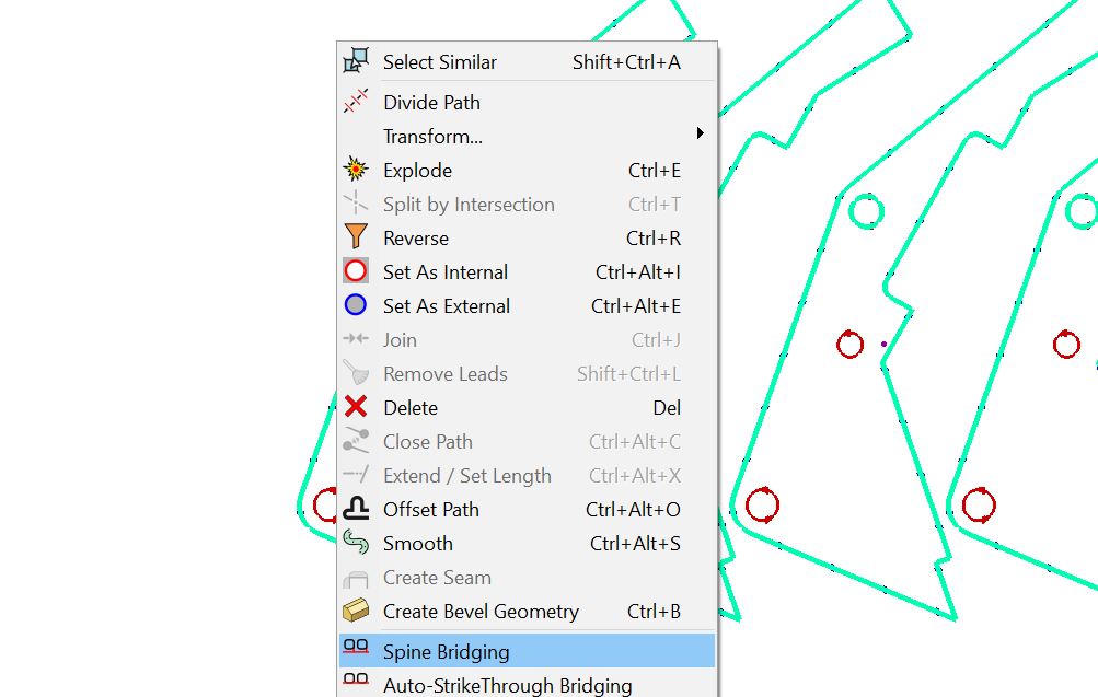
The mouse cursor will change to an array of squares, and a line will appear adjacent to the parts. You can change the location of the line by moving the mouse. DON'T CLICK UNTIL STEP 6. Once you Click to select a location for the line it will form the basis of the bridge between the parts.
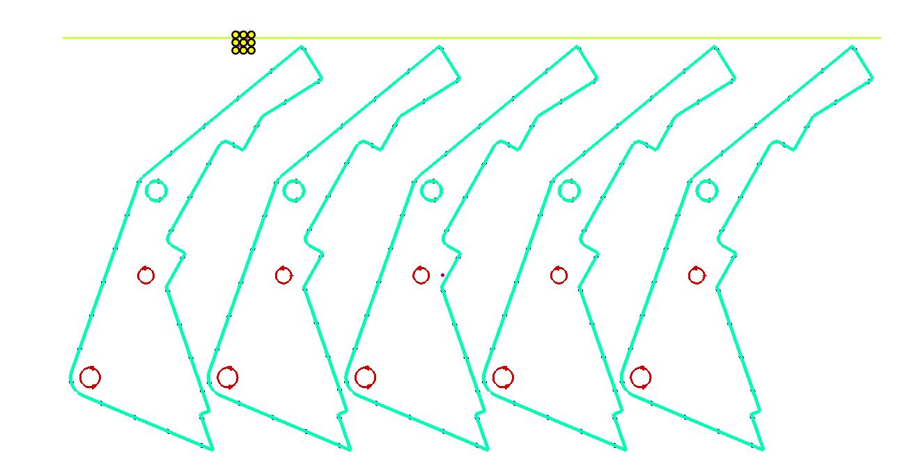
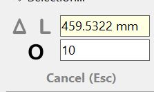
5On the menu bar you will see a number appear with an O to the left of it; this is the offset distance between the parts and the bridge line. Change the offset value to 10 by typing 'o 10' or clicking in the box and typing 10.
6Place the line above the parts by moving the mouse there and clicking once, or pressing ENTER. PrimeCut will create new geometry to bridge the parts.
7If the Bridge Cut Overlap window appears, enter 0.00mm and click OK.
8Click OK to add new area layer.
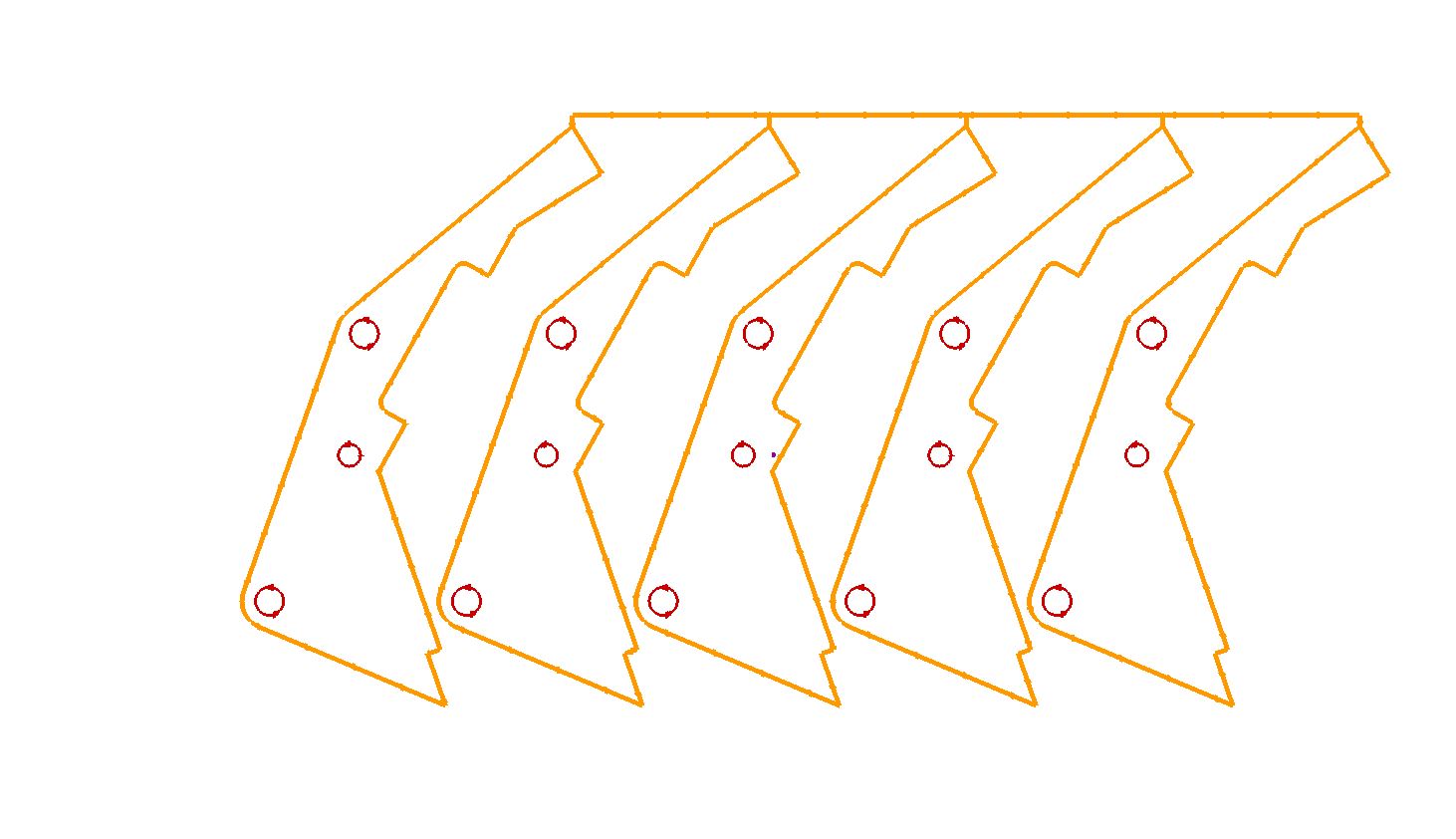
You can see that the outer paths of the parts have been joined to form a single path.
We can now apply processing to the part and tidy it to finish the spine bridge.
The single path created by Spine Bridging is an open path, the "No Kerf For Open Paths" option on either the cutting tool or beveling tool is ignored so there is no danger that the path will be processed with no kerf.
The tools options are overridden by a 'Kerf Left' Geometry hint on the open path.
9Go to the Processing editor tab and Click the Process All button. When the processing options dialog is displayed, Click the Show Options button.
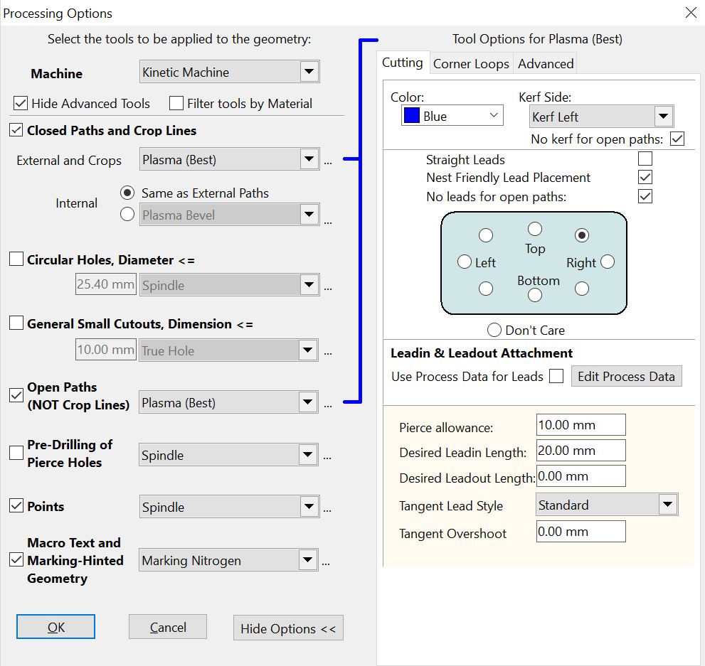
10On the Leadin & Leadout Attachment selector choose Top Right as shown above. This placement will make it easier to tidy the part after processing.
11Accept the settings on the processing options dialog (the bridging will have the same effect regardless), and press the OK button to process the part.
Because we don't need to cut the bridge in our cluster part twice, the path is no longer a closed loop.
We will now look at the cutting process in the NC Code editor. This editor generates a cutting simulation based on the NC code produced by the processing editor, and is therefore an excellent way to view the process, as it will occur on the machine.
12Click on the Schedule editor tab.
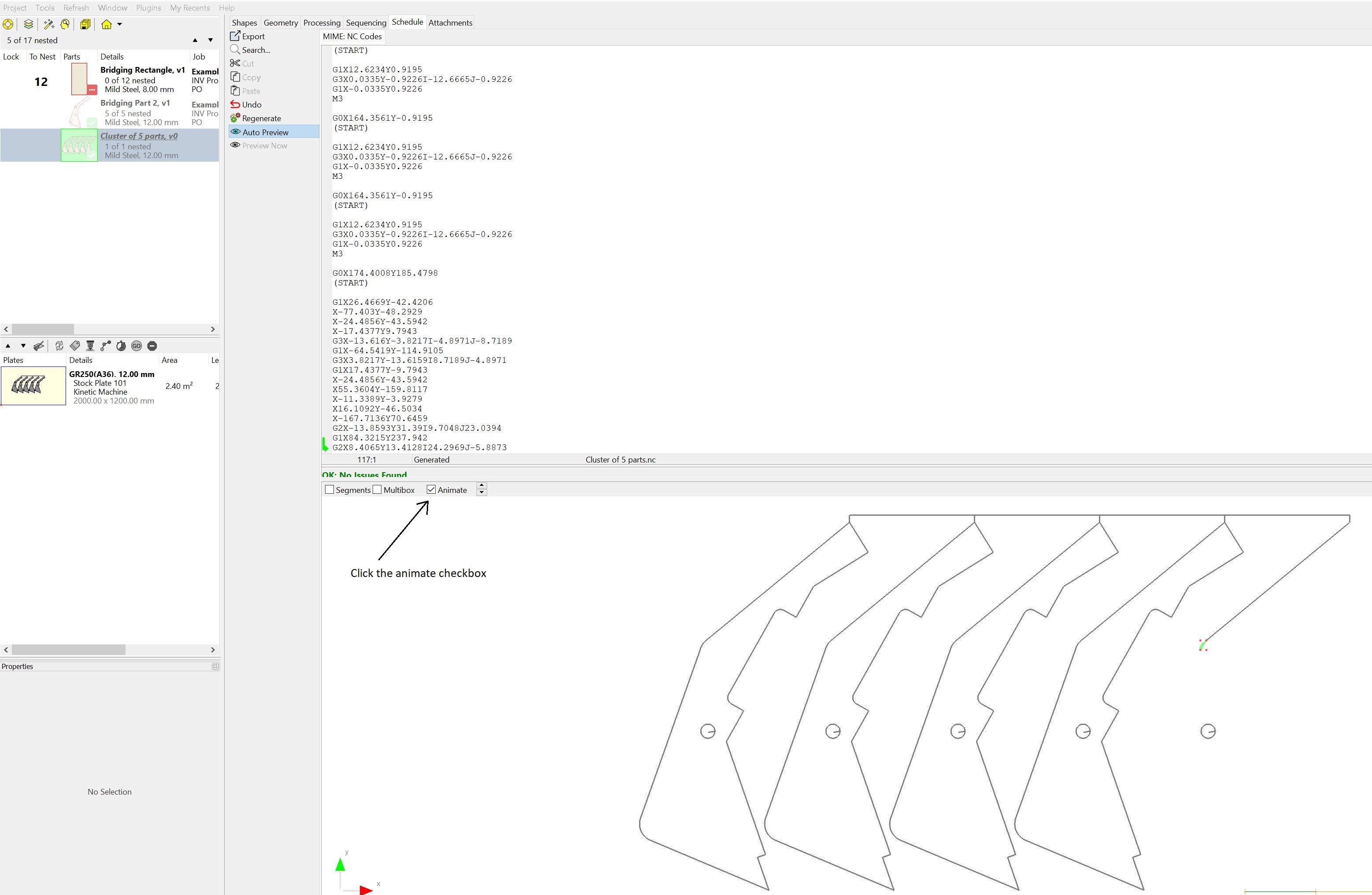
13Tick the Animate checkbox, and the process will be simulated.
The default offset distance between the spine and the parts can be changed by clicking on the Options button and selecting the Geometry tab. Look for Default Spine Offset under the Bridging Options heading.