On thick mild steel cut with oxygen, a sharp corner is a heat trap. The torch slows to negotiate the corner while the exothermic FeO reaction keeps running, so heat builds up faster than the plate can carry it away. The result is a rounded, over-burnt corner and often a widened kerf on the segment leaving it.
A cooling point mitigates this. At each sharp corner PrimeCut emits a short block into the NC program that inhibits the laser, dwells for a set time, then re-enables it. Assist gas keeps flowing at cut pressure throughout, so the dwell actively cools the corner rather than just pausing there.
Cooling points add no geometry. The motion path through the corner is exactly the same as it would be without them — only the time spent at the corner and the laser state change. This is what distinguishes them from corner loops, which shed corner heat by adding an overshoot detour.
Tool settings
Cooling points are a per-tool property. Open Processing Options, select the cutting tool, and go to the Advanced tab. The settings live under the Cooling Points group:
Setting |
Meaning |
Cooling Points |
Master switch. When on, cooling points are placed automatically at every sharp corner of the cut path. Off by default. |
Cooling Point Dwell (s) |
How long to dwell at each cooling point, in seconds. Default 0.3 s; 0.1 – 1.0 s covers most work. Longer dwells cool more but cost cycle time on every corner, and an over-long dwell can leave a visible witness mark. |
Cooling Point Angle |
Corner angle threshold, default 90°. Corners sharper than this get a cooling point; shallower ones are left alone. The test is on the deviation from straight-through, so internal (concave) and external (convex) corners of the same sharpness are treated alike — unlike corner loops, which only apply to external corners. |
Cool. Pt. at Leadin End |
Also drop a cooling point where the lead-in joins the cut path. On by default: the lead-in junction is a genuine sharp corner and normally wants the same treatment. Turn it off if the pierce heat there is already handled by the pierce cycle. |
NOTE: The lead-out end of a closed path is never given a cooling point. It revisits the closure point that has already been cooled on the way in, so a second block there would only add cycle time.
Where cooling points appear in the processing window
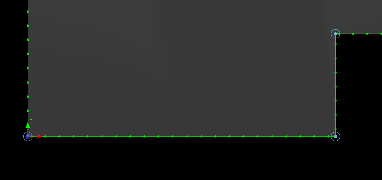
Cooling points are drawn on the cut path as a small light-blue circle with a centre dot, one at each corner that qualified. Here a rectangular part has picked up cooling points at its corners:
Zoomed in, the marker sits exactly on the corner vertex — the path itself is unchanged:
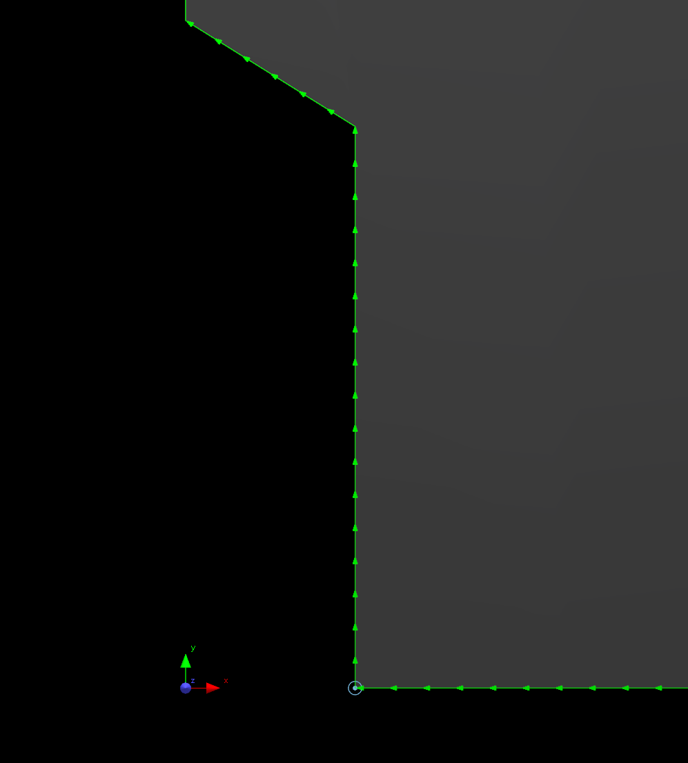
NOTE: The marker is a display aid only. Use it to confirm the angle threshold is picking the corners you expect before committing to a cut.
NC output
At each cooling point the post-processor emits three blocks of tool code, in order: Pre-Cooling Point, At-Cooling Point, then Post-Cooling Point. These are ordinary tool code memos on the Tool Codes group, alongside Pre-Corner Loop and the rest, so a site can change them to suit its controller.
The defaults are:
•Pre-Cooling Point — M84 (PWM inhibit on: laser off, gas still flowing)
•At-Cooling Point — G4 P{dwell_sec} (dwell)
•Post-Cooling Point — M83 (PWM inhibit off: laser back on)
The {dwell_sec} token is substituted with that cooling point's dwell time in seconds wherever it appears in any of the three memos.
With the defaults and a 0.3 s dwell, each cooling point appears in the NC preview as three blocks immediately before the move that leaves the corner:
M84
G4 P0.3
M83
Limitations
Two cases where cooling points will not appear:
•Do not enable cooling points and corner loops on the same tool. A corner loop replaces the sharp corner with a detour, so there is no longer a corner vertex for the cooling point to attach to and no block is emitted. In practice the two do not overlap anyway: cooling points are for thick mild steel in oxygen, corner loops for thick stainless in nitrogen.
•Cooling points are not placed on offset or partial (trimmed) processes.
See also Automatic Corner Filleting in NC Output.