The display style of the dimensions can be easily changed.
The most obvious style change would be the size of the text. Because the text size is an absolute value, it is sometimes inappropriate for large or small parts. This is another reason why when importing a part it is time saving to import its dimensions (i.e. tick Auto Dimension Part) as well, as an appropriate dimension scale is usually added.
This is an absolute value, meaning that if a very large part is imported the dimensions can be very small relative to the part.
1Open the Workorders mode.
2Search for and open the Part Dimensioning workorder (enter Part Dimensioning under Invoice Number and Click Refresh).
3Double-Click on the Dim Part 4 part from the explorer window on the left.
4If there are dimensions on the part select them and press DELETE.
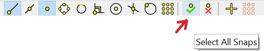
5Click the Select all Snaps button.
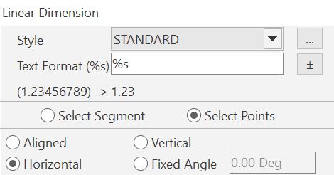
6Click the Create Dimension button; select Linear Dimension.
7On the dialog, choose the following options:
8Dimension the overall length of the part:
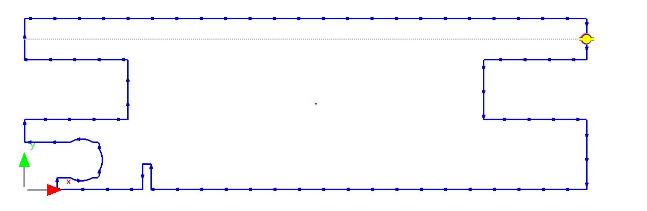
Notice that the dimension text is barely visible. This is because the part is over two meters long, but the text is set to a few millimeters.
9Select the dimension (if it is not already) and then Click the '...' button on the properties dialog:
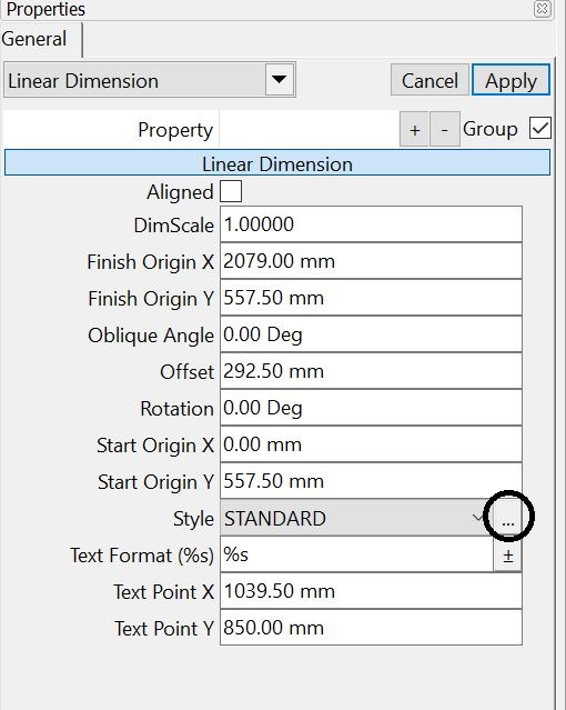
This will display the following dialog:
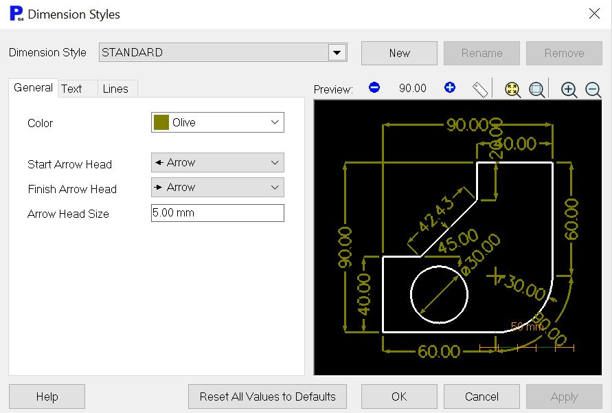
If under dimension style 'Large' is available, select it and Click Remove (top right button). (We want to add this to the database.)
Ensure STANDARD is selected as shown above.
10Click on the number between the plus/minus buttons:
![]()
11Change the Preview Scale to 2880 (i.e. 2880mm), and Click OK.
This will change the scale of the preview picture to that of our part.
It would be useful to create a new dimension style that we can use for large parts such as this.
12Click the New button.
13Enter 'Large' as the name of the style and Click OK.
14Change Arrow Head Size to 50mm and Click the Apply button.
15Click on the Text tab:
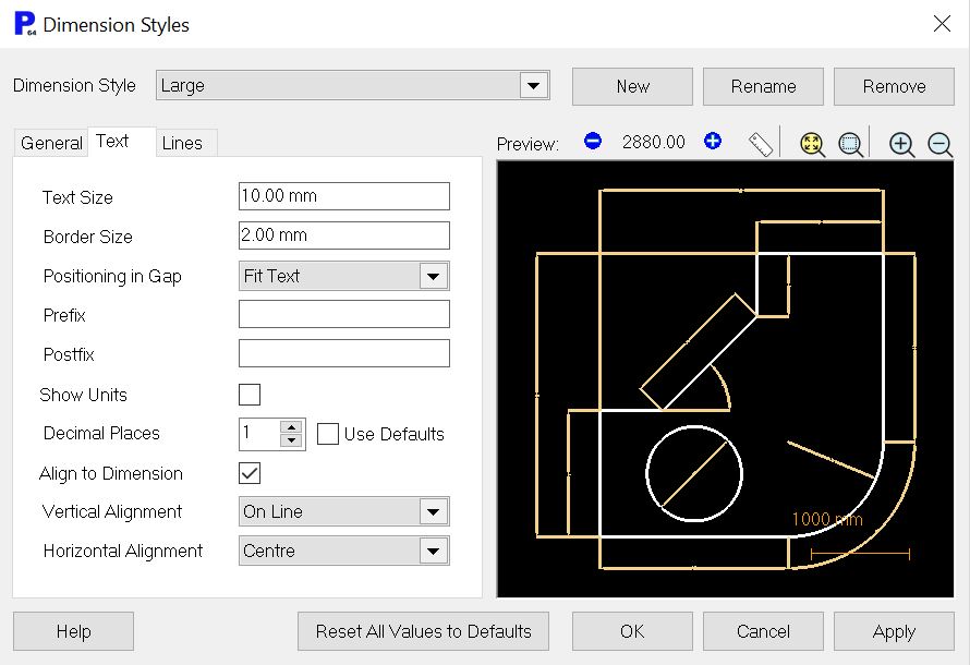
16Make the following changes:
Text Size: 40mm
Border Size: 10mm (to increase the space around the text)
17Click the Apply button. The text is now visible.
18Click on the Lines tab. These can be scaled appropriately also.
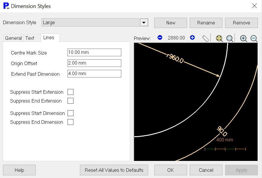
Magnify the preview window as shown above so the effect can be seen.
19Make the following changes:
Center Mark Size: 50mm
Origin Offset: 20mm
Extend Past Dimension: 20mm
20Click on OK to close the Dimension Styles dialog.
We can now add another dimension using the newly defined style.
21From the geometry editor toolbar Click the Create Dimension button; select Linear Dimension.
22On the dialog, choose the following options:
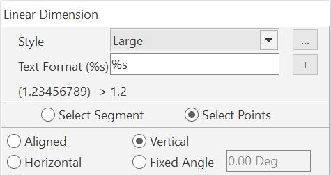
From the Style drop down box choose Large.
Create by: Selecting Points
Dimension Line Angle: Vertical
23Dimension the overall height of the part:
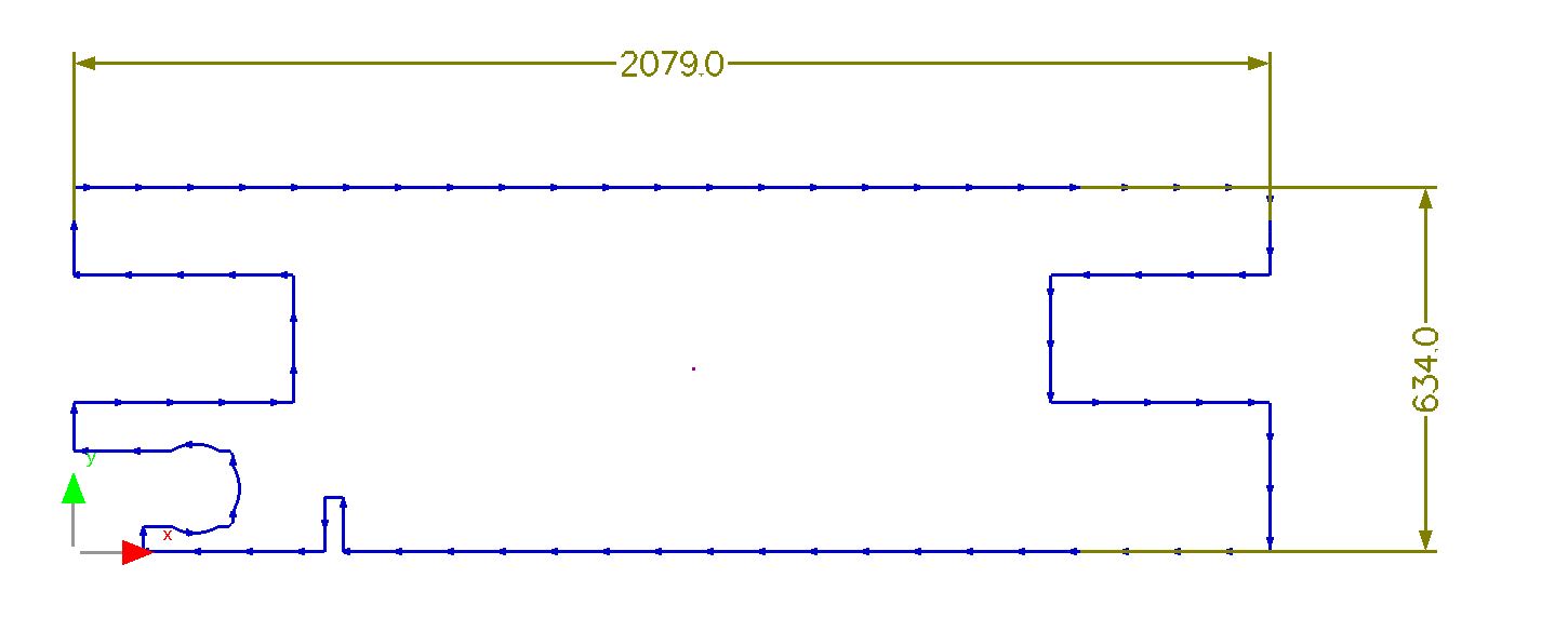
24Close the mode without saving.