Here we will import a fully dimensioned part that has been stored as a DXF file. Most dimensions will be deleted, but we will leave those that we want to appear on the part report.
This example is designed to teach you how to use dimensioning. In a real situation far fewer dimensions would be used, and the main purpose would be to confirm that the scale of the part is accurate. This would indicate that the kerf settings are correct.
1Open the workorders mode.
2Create a new workorder
3Select 'Tut Customer 1'
4Click the import parts button. 
5Navigate to the NE Tutorial parts folder which should be found (in a standard installation) in C:\Program Files\PrimeCut4\NE Tutorial Parts.
6Select the FULL_DIMv2.dxf. Tick Auto Dimension Part and click open.
Alternatively, if you NE Tutorial Parts does not have FULL_DIMv2.DXF, open the Part Dimensioning workorder and select the Full_Dim part.
7Double-click on this part in the parts area window on the left to load it into the Geometry editor.
8The part should be loaded with the Show Dimensions button depressed. If the dimensions are not visible, Click this button to show them.
9Select one of the dimensions, and in the properties window, press the ... button ![]() under Style. (if no properties window shows, right click and click Show Properties from the pop-up context menu)
under Style. (if no properties window shows, right click and click Show Properties from the pop-up context menu)
10Click yes to add the style to the styles list.
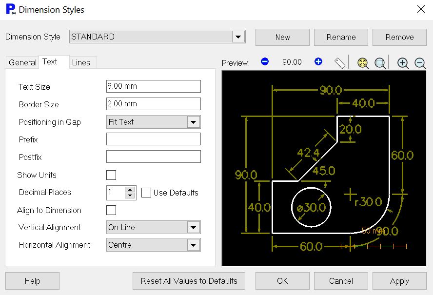
11Click the Text tab and change the number of Decimal Places to 1. Click OK.
12 The part should appear as below:
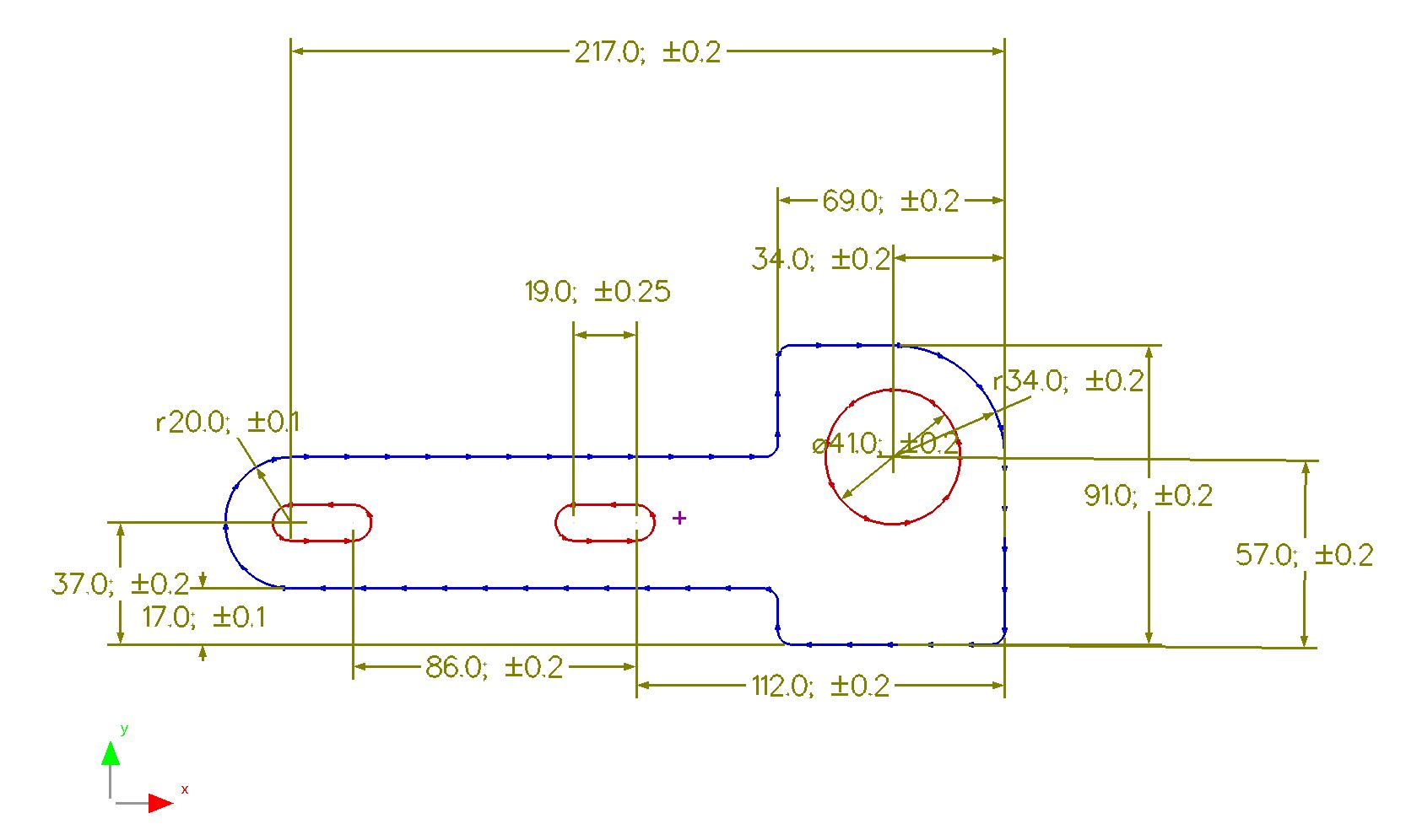
If we are to produce a part report for our machine operator, then we need to reduce this to a few critical (and measurable) dimensions. The actual dimensions chosen will depend on the particular requirements. In this case we will look at the outside linear dimensions, and the size and placement of the hole.
13To delete a dimension, simply select it and press the DELETE key. Delete dimensions until you get the result shown below:
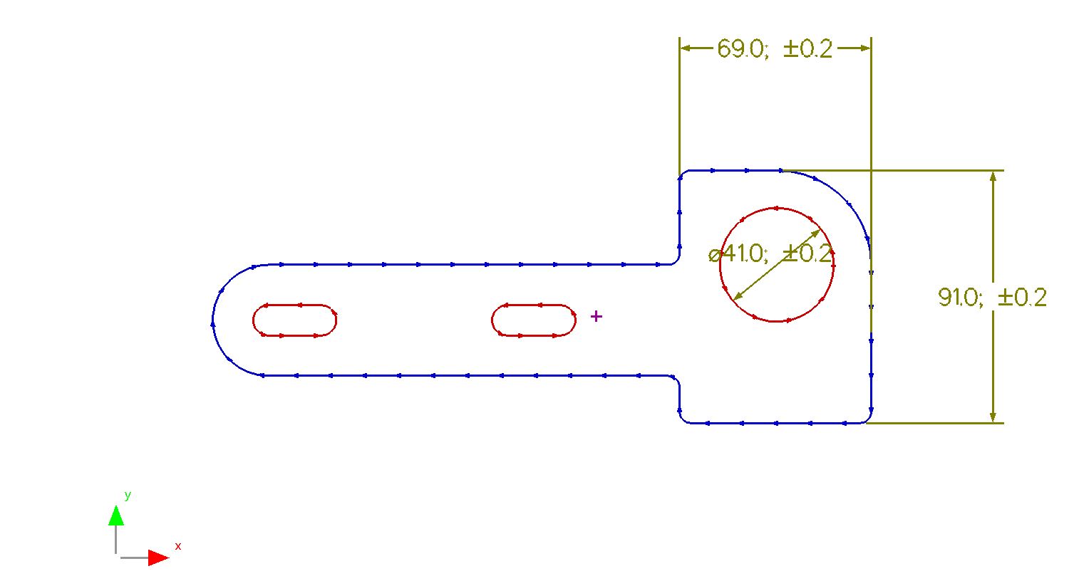
We now want to add dimensions for checking the placement of the hole.
14Click the Select all Snaps button.
15From the geometry editor toolbar Click the Create Dimension button, and select Linear Dimension.
16On the linear dimension dialog that appears, press the +/- button. Enter 0.3 as the tolerance and Click OK.
17On the dialog choose the following options:
Create by: Selecting Points
Dimension Line Angle: Vertical
18Place the dimension as shown:
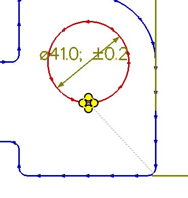
19Place another linear dimension to determine the lateral location of the hole. Use the same options as the last dimension, except for the Dimension Line Angle, which should be Horizontal.
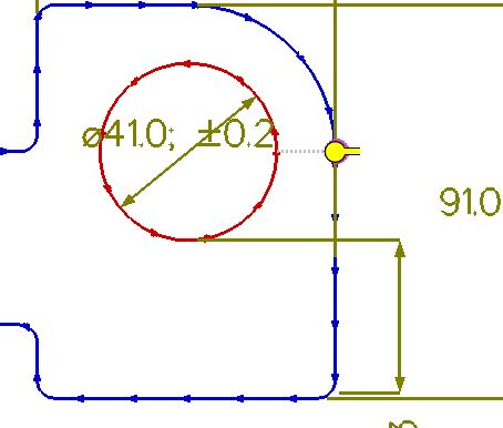
Notice that these dimensions have been placed where the radius and the line meet. This helps to separate them from the lines of the part.
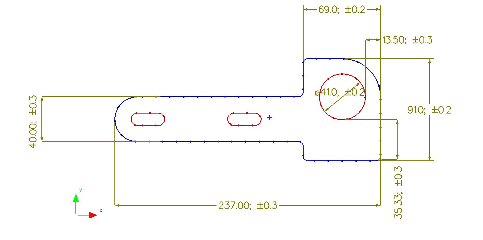
20Using similar techniques, place dimensions for the overall length of the part, and the width of the tongue. The result should look similar to the example below:
It may be that one of the right angles is critical to the integrity of the part and therefore needs to be dimensioned also.
It is unlikely that you would place this particular dimension in a real situation, but it will show you how to use an angular dimension.
21From the geometry editor toolbar Click the Create Dimension button, and select Angular Dimension.
Leave the settings as they are.
22Place the dimension as shown below.
Finally we will place a Leader Dimension, which can be used for any sort of note you would like to appear on the part report.
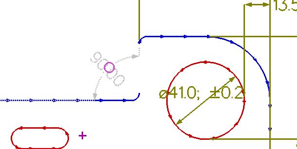
23From the geometry editor toolbar Click the Create Dimension button and select Leader Dimension.
24Type the following text into the Leader Dimension dialog:
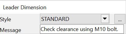
25Attach the leader dimension to the top of the left hand slot:
26Home without saving.