The final (and most critical) factor involved in successful bridge cutting relates to how the parts are nested on the plate. By giving some thought to this process you can use the weight of the plate to prevent partially cut parts from moving and thereby ensure the success of the cut.
Here are a few points to keep in mind:
▪Do not make bridge cuts excessively long. A good general guide is to keep them to about a metre (or three feet) in length, although if you have a 1.2m wide plate it would be ok to make a bridge span this distance.
▪Be conscious of the amount of plate that is left to hold your parts. If you are nesting your bridge on a small remnant of plate, then there will be a higher likelihood of movement and you should make your bridge cut smaller. If on the other hand you are dealing with a large plate, then you could make your bridge cut over a metre long because there will be very little chance of the plate moving.
▪Nest your bridged parts so that the last cut to be made is facing the 'meat' of the plate, not the edge.
▪Try to use Manual Strikethrough Bridging because this will give you more control over the placement of the bridging lines.
▪Process the bridge cut before nesting on the plate so you have more control over leadin placement.
The following tutorial will help to illustrate the above points.
1Open the workorders mode and open the workorder with invoice number Processing: Bridging.
2Select the workorder from the workorders explorer and Click Open Workorder in Nesting.
3Click the Open Plate button in the top left corner of the screen. Click Create New Plate. Enter the following details and Add to Stock and Close.
Plate Material |
GR250(A36), 8.00 mm |
Width |
800 mm |
Length |
1000 mm |
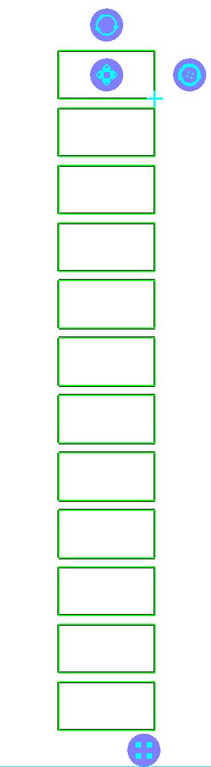
4Nest the Bridging Rectangle part on the plate (rotating is as necessary) and create the array shown below.
5Select the parts, right-click and select Quick Cluster from the popup menu. Right click again and click Add Cluster to parts list.
6Double-click on the newly created cluster in the parts menu to open it in the Geometry editor.
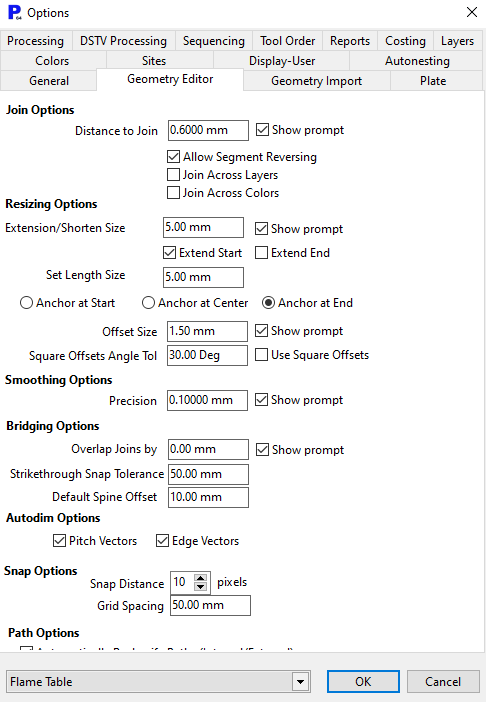
Click on the Options button on the left toolbar. Under the Bridging Options heading you will find a Strikethrough Snap Tolerance value, change it to 50mm (2"). This controls how close you must be to the edge of the part in order for the bridge line to snap to that edge. By changing it to such a large value we have ensured that the bridge will snap to the edge even if the line is some distance away
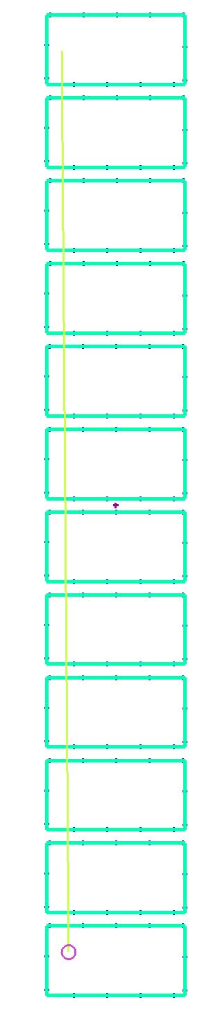
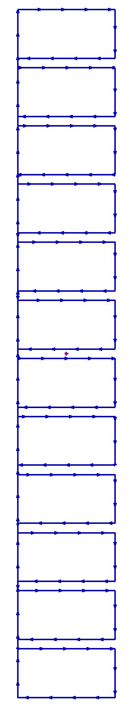
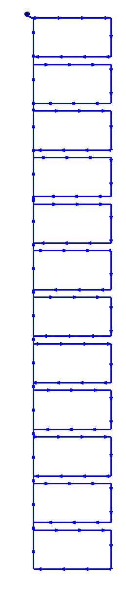
7Select all of the parts and press the Strikethrough Bridging button on the editor toolbar, then draw the line shown in the below left. On the StrikeThroughBridging popup, select Chain cutting and leave bridge overlap value as its default value and click OK. This will result in the bridge shown at the right.
8Now go to the processing page and click process. Use a plasma or gas process and select the Top Left for Leadin and Leadout Attachment. Click the OK button. By placing the leadin and leadout at the top left corner we have ensured that the main bodies of the parts are cut first, and the bridge that joins them all is cut last.
9The next issue is how we nest this on the plate, as mentioned before we want to make sure that the parts are held in place by the weight of the plate. On this basis the bridge cut we have just created should be nested on the right hand side of the plate as shown below.
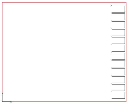
This shows the cut partially completed, and it is clear that the metal that makes up the parts is very unlikely to move. If we nested it on the left hand side of the sheet then there would only be a strip of metal holding the parts and this would probably move as a result of heat deformation as illustrated below.
If you did want to nest the part here then you would simply need to rotate it by 180 degrees.
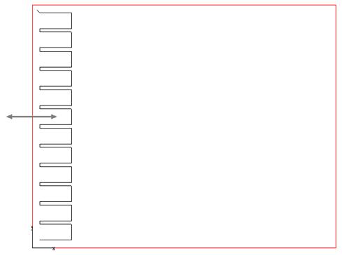
The arrow in the above illustration shows the movement you might see in this case. If the strip flexed to the right you would end up with a thin strip between all of the parts, and would find that they are slightly over size.
10Close the mode without saving.