NOTE the new QuickPrep function has greatly simplified this procedure.
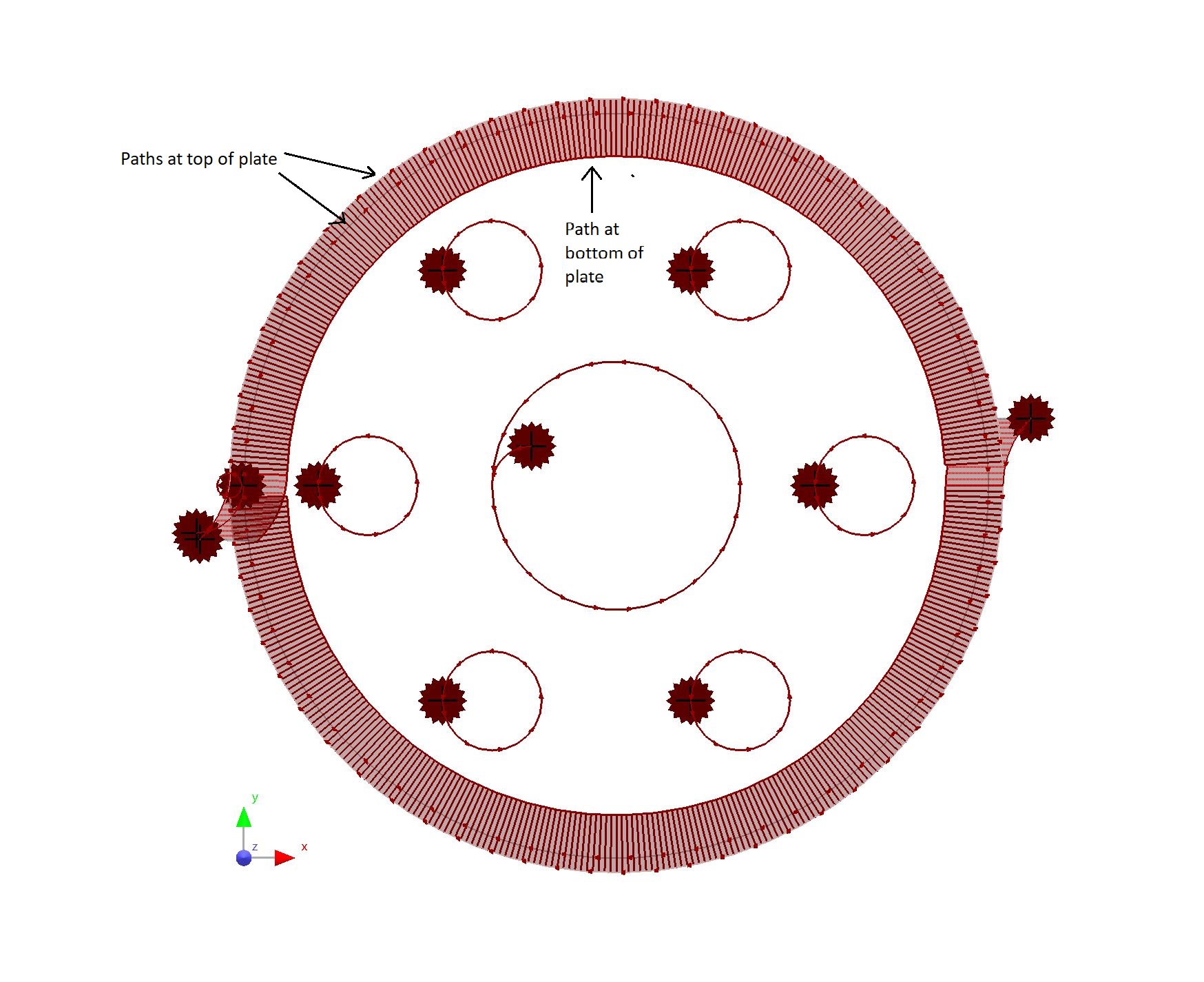
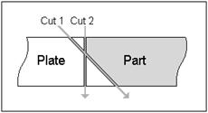
In this exercise we will use the multiple bevel wizard to create a part profile with a negative bevel, and a land at the top. The desired geometry is shown below.
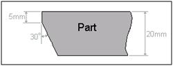
We will not work through the process of creating a 'top bevel + land' because it is very similar to this exercise. The only differences (which will be highlighted as we reach the relevant points) are that at the processing stage a positive Initial Bevel Angle would be entered, and the outside cuts would need to follow the opposite sequence.
One thing to be aware of is the need for the part to be attached to the plate when making cuts. In this exercise we will use undercut on the bevel cut so that the part will remain attached to the plate until the vertical cut is completed. We will create this undercut in the geometry editor by changing the bevel path to create an open path.
1Make sure you have opened the Bevelling Tutorials invoice number workorder.
2Double-click on the Bevelling Flange.
3Click on the Geometry tab to go to the Geometry editor.
4Select the outside path of the part and right-click to display the popup context menu.
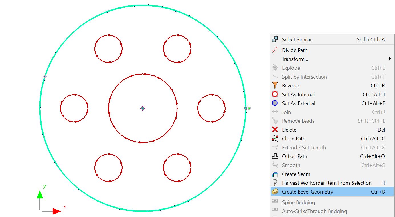
5Select Create Bevel Geometry from the menu. Click OK to create new area layer. Select Bottom Bevel+Land tab and enter the details shown below and click OK.
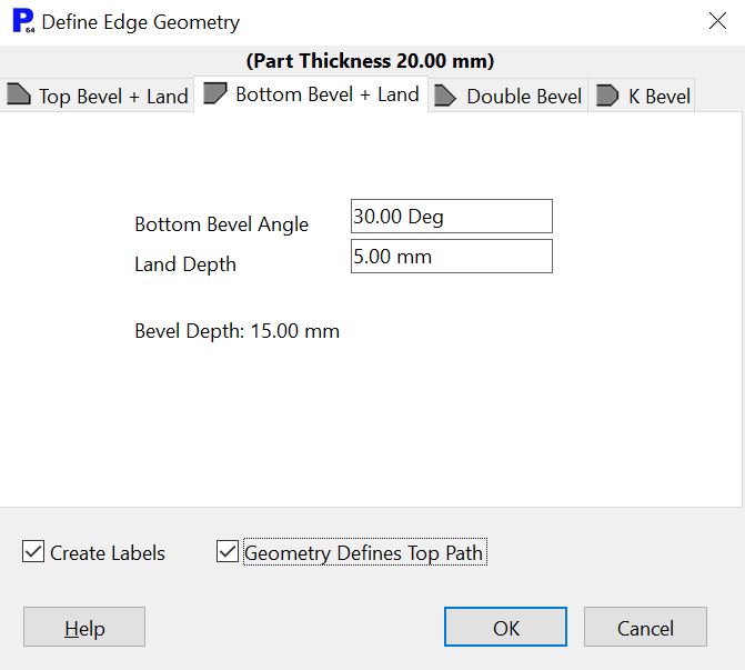
Although we are creating a negative bevel it is not necessary to enter a '-' sign at this point, since it is taken as a given. Note that PrimeCut calculates the depth of the bevel (15mm) and shows this value.
If leader labels are required (recommended), tick the 'Create Labels'.
6Click the OK button.
7Click on the Show Dimensions button (unless it is already depressed).
8Click on the Auto Zoom button to view the part and notes.
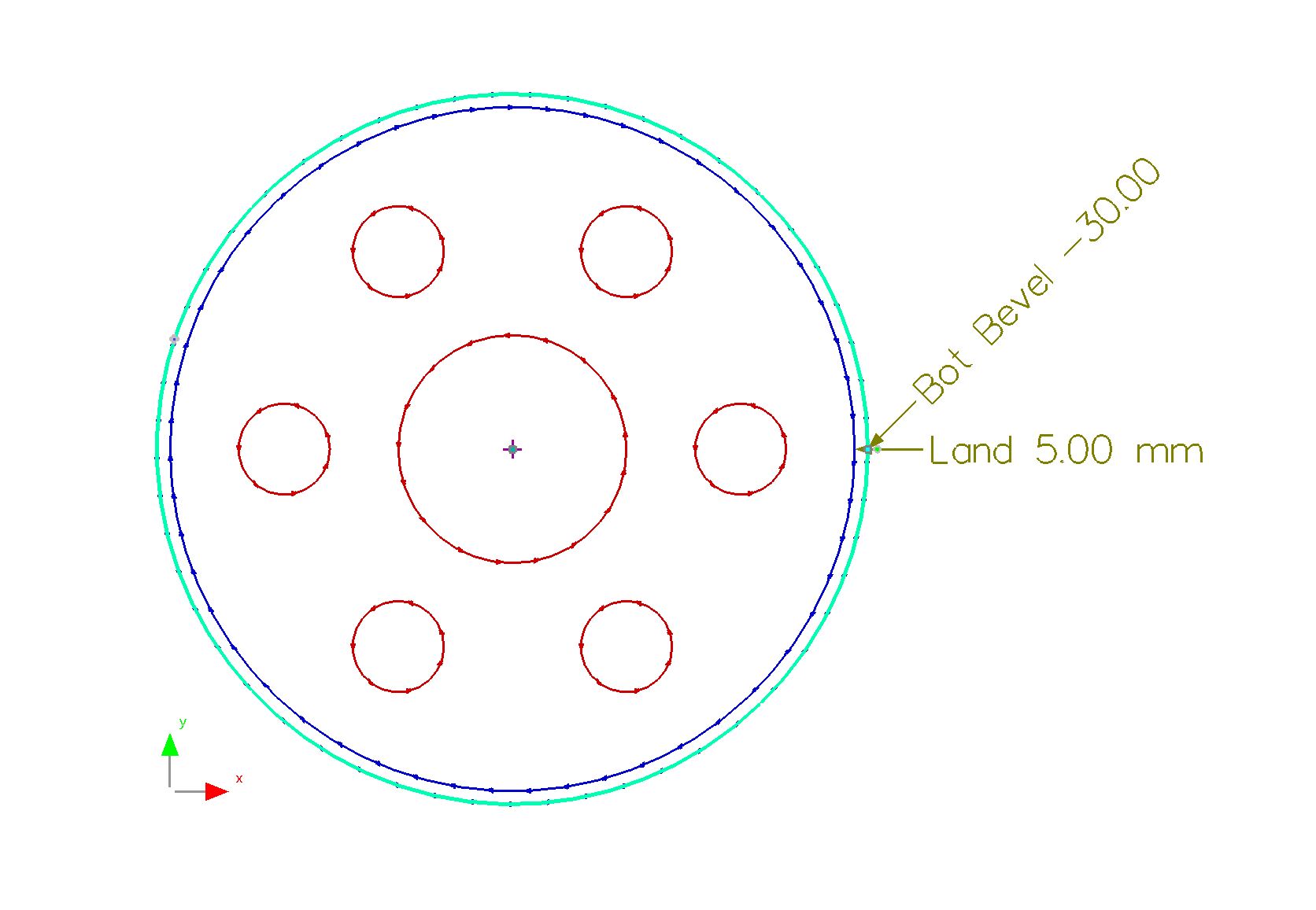
PrimeCut has created notes on the part to show what each of the newly created geometry lines relates to.
9Select both external paths.
10In the properties window, under the Hints field, press the View button. The following window should open.
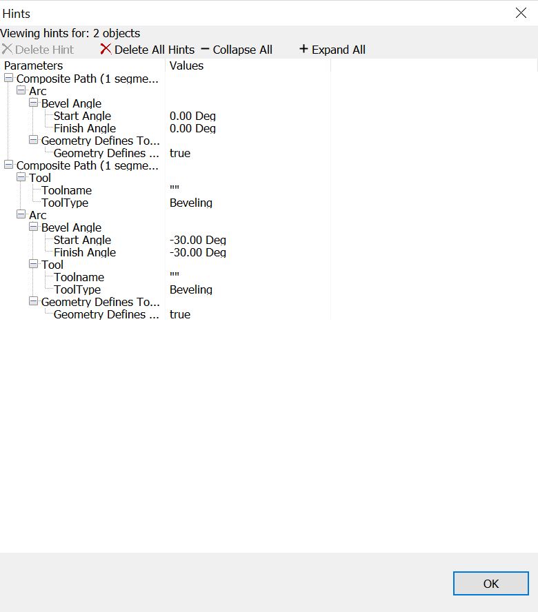
Hints inform the Geometry Processor's settings on how to process the bevelled path. You have the option of deleting hints, in which case the lines will be treated as normal by the Geometry Processor.
We can now modify the bevel geometry to create the desired undercut so that the part will remain attached to the plate after the first cut.
11Select the outside path relating to the bevel. At the right hand side you will see a small white outlined circle.
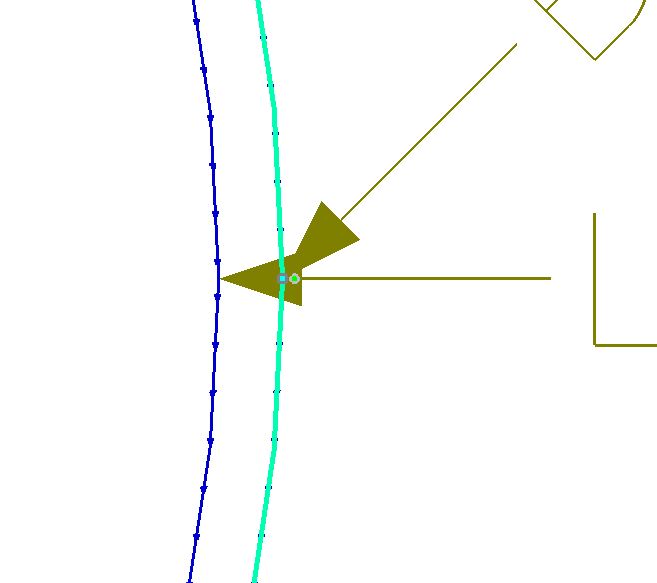
12Drag this circle (as shown by the arrow above) upwards to create the split required for the undercut.
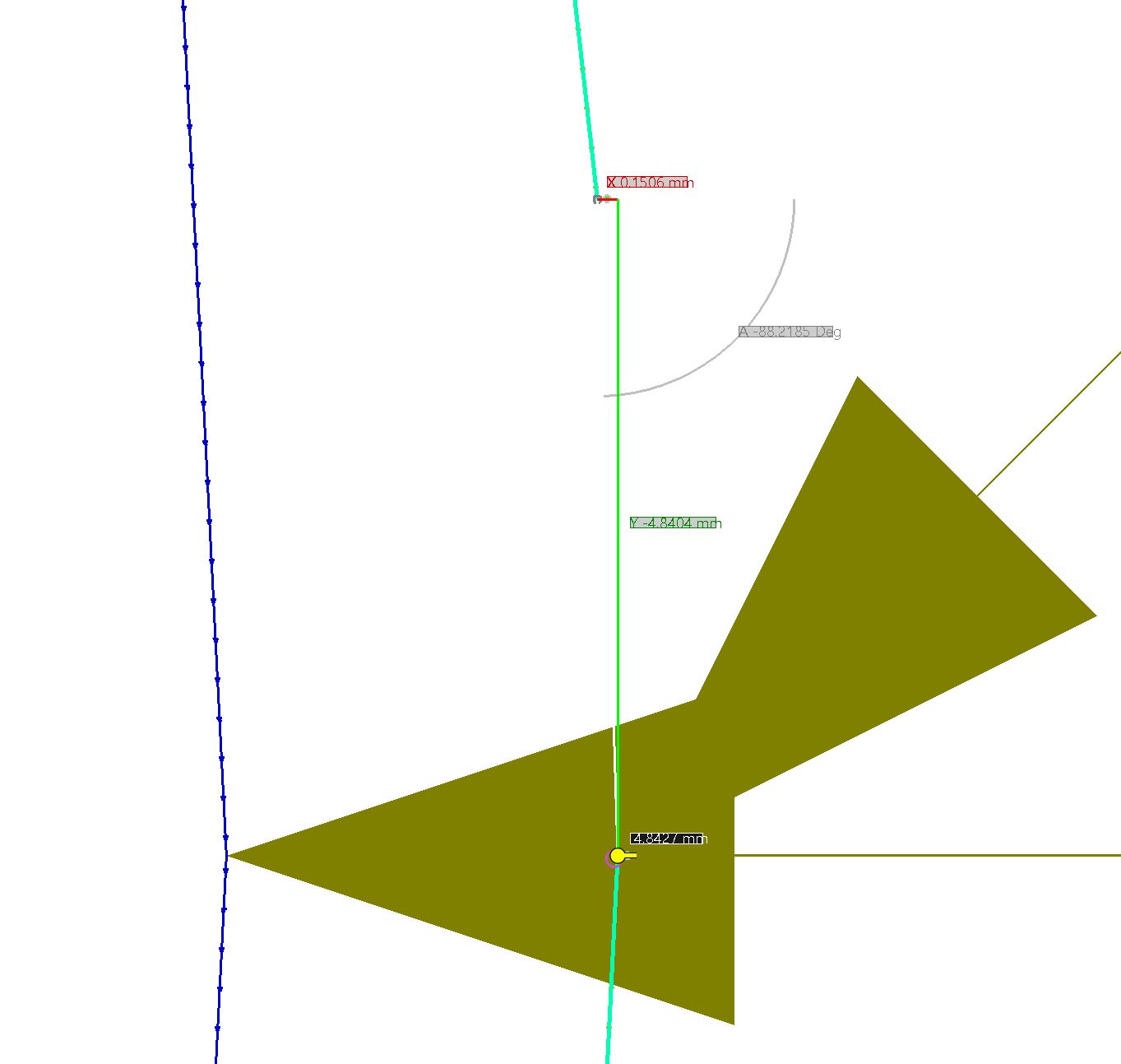
13Zoom in on the split.
14Click on the Measure button.
15Measure the size of the split and change the spacing until the split is approximately 5mm.
If your part requires more than 1 tab, and/or you find the above approach undesirable, you may want to create another tab:
16Select the Centre Radius Circle tool.
17Click to place the center on the opposite outermost edge of the flange.
18type 'L 2.5' to set a radius of 2.5mm and Press ENTER.
19Use the Trim tool to delete the line passing through the circle we have just drawn and the circle itself.
The two segments of the line that was split should share the same Hints properties
The geometry is now ready to be processed.
20Go to the Processing editor tab.
21Click on the Process All button.
To lower the toolchanging and rapids time we will process the internal circles of this flange with the bevelling torch too.

22Enter the details shown above (although you should only need to change the following):
Apply Plasma Bevel to the internal paths.
Ensure the Closed Internal Paths > Initial Bevel Angle field is 0.00 Deg
Change the Open Paths > LeadOuts Size 0.0.
Untick the Open Paths > No Leads for Open Paths
The hints override the following Processing Options in this case for the paths that have been edited by the Bevel Geometry Wizard. The other paths are processed the normal way.
Initial Bevel Angle (the angle is part of the geometry as Bevel Angle Hint)
No Kerf Open Paths (it is overridden by the Kerf Left Hint)
Since we are happy with the other presets, we can move on.
23Click the OK button.
Recall ALT + right-click can be used for rotating. Z, CTRL+ALT+Z, or Click AutoZoom to get back to a front view.
You will see that bevel processing has been applied to the part. If PrimeCut has used straight lead-ins for the open paths, then our effective undercut will be smaller which is not desirable. We can remedy this by changing the Leadin Style from 'Line' to 'Arc'. Otherwise you may skip to step 7.
For each of the straight outer leadins:
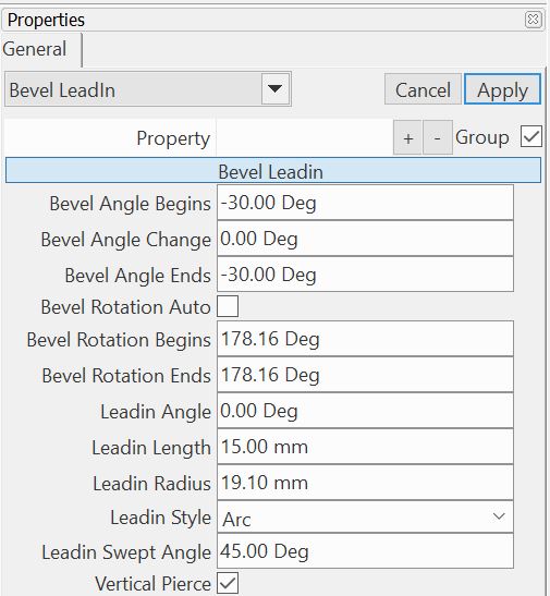
24Use the confirmed selection technique to select the outer straight leadin. (Hold down ALT key and click on the leadin. Click Bevel LeadIn, then click Select for the straight Bevel Leadin)
25In the properties window select Arc as the Leadin Style and click the Apply button. Do for each LeadIn.
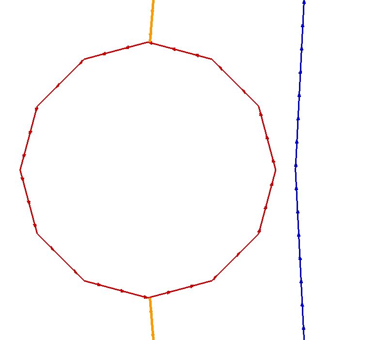
26Zoom to LeadIn for the inner circle. Here we see a potential problem that can occur, as shown below:
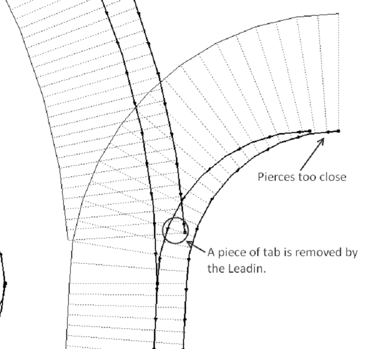
If the pierces are too close, the height sensor may be fooled by the previous cut or dross from it.
If too much tab is removed early on, then the part may be ill-supported for the rest of the cut.
This example isn't particularly bad, but we will deal with it anyway by moving the leadin for the vertical bevel lower.
27 Select the Place Leads tool from the toolbar.
28Click lower on the inner circle path to place the leadin as shown.
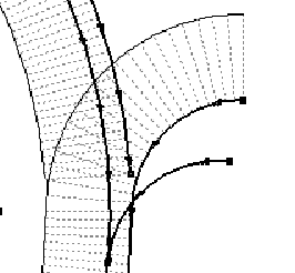
29Press ESC to deselect the tool.
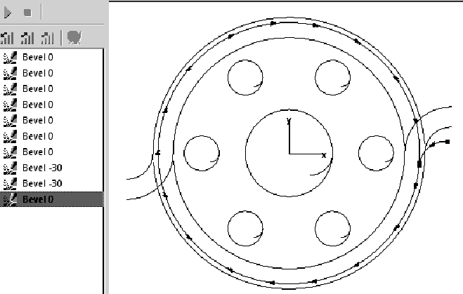
We will now sequence the part so that the cuts will be executed in the order shown below. This is the order we have been assuming, since the first cut always needs the tabs, to hold it in place for the second cut. Bevels should be cut in order of increasing angle, so that by the time the torch reaches the disruptive air gap created by the previous cut, it has already cut what it needed to on the part. When Geometry Defines Top Path is set, this equates to outer most paths first.
30Click on the Sequencing Editor Tab.
31Click on the items in the sequence to see what process is being used. Rearrange by dragging and dropping the list items. Make the final external vertical cut the last cut of the sequence and sequence the two -30 degree bevels directly before it.
The part is now correctly sequenced and can be nested on a plate. As for all multiple bevel parts you must remember to retain this processing, and sequence the plate on a 'part by part' basis so that the part sequencing does not change.
32Proceed on to the next tutorial, or close the mode without saving.