NOTE the new QuickPrep function has greatly simplified this procedure.
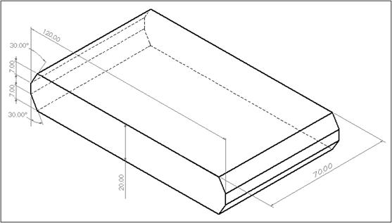
In this exercise we will use the multiple bevel wizard to create a K bevel (sometimes called a Y-Bevel) The principle is similar to that of the bevel with land, but given that it involves three cuts there are some details that require extra consideration when it comes to processing the part.
We will bevel two sides of a rectangular part from the PrimeCut shapes library. To make this possible we will need to 'explode' the geometry so that the bevel wizard can be applied to just two sides of the rectangle. Once the wizard has been used to create the extra geometry for the bevel we will change some of the lines in order to create a closed path for the final cut.
1Open the Workorders mode, and open the workorder with the invoice number 'Bevelling Tutorials'
2Open the K Bevel Rectangle part from the parts explorer on the left.
3Go to the Geometry editor tab.
4If the part is already processed, press the Revert button.
5Select the outline of the part, right-click to display the popup context menu and select Explode.
6Select both the top and bottom path. A 'crossing rectangle' (right to left) is the easiest way to do this.
7Right-click to display the popup context menu and select Create Bevel Geometry. Click OK when it warns you an area layer has been created.
8Click on the K Bevel tab, enter the details shown below and click the OK button.
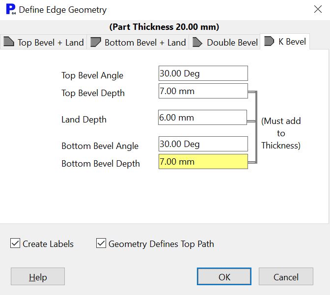
The extra geometry that is created for the positive bevel can be pre-offset by selecting the 'Geometry Defines Top Path' option. This can make visualizing cutting paths in the Geometry Editor easier.
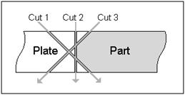
Now we will change the geometry so that we have four open paths, and one closed path for the final cut. A simple method would be to close the original rectangle, but this would not give us the desired cutting sequence. The figure below shows the sequence we should use to cut the K-bevel, you should experiment with other sequences, but our experience has shown that this one produces the best results. By changing our geometry we can make a closed loop that includes cut 3 as well as the vertical sides of the part, so that they can all be cut using one pierce.
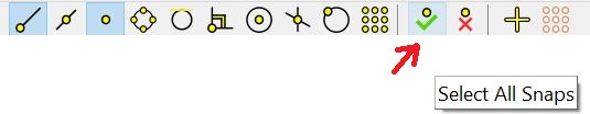
9Click on the Select All Snaps button.
10Select one of the vertical lines of the rectangle.
11Now we will shorten the vertical lines to make a closed path to encompass the straight cutting and the negative bevel. Click on the bottom end line of the vertical line and place it at the end of the next horizontal line up, shortening the vertical line.
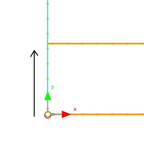
12Click on the top end of the vertical line and place it at the end of the next horizontal line down.
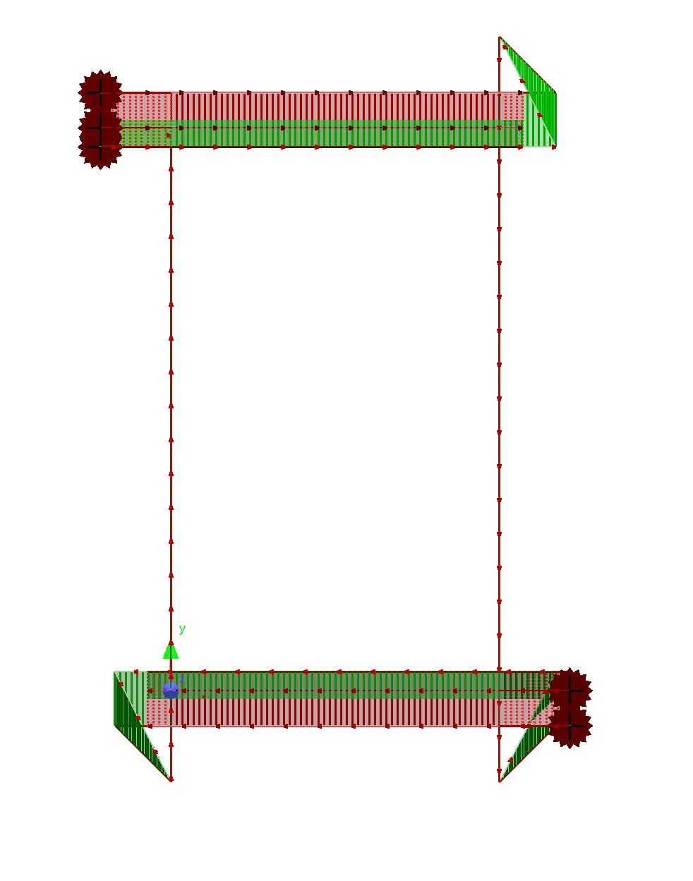
13Repeat with the vertical line on the other side of the part, top and bottom. The geometry should look like this:
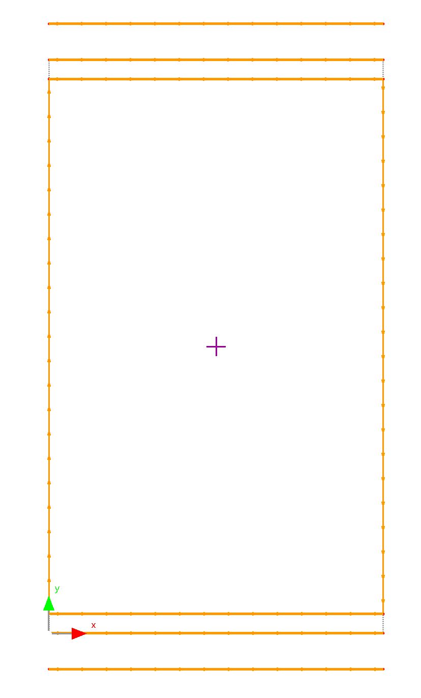
( The bottom left has the origin visible )
14With a vertical line selected join the loop (CTRL + J, or right-click and Click Join from the context menu).
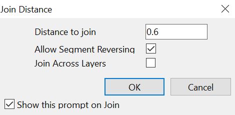
15Click OK to join the loop. This Confirm box should appear:
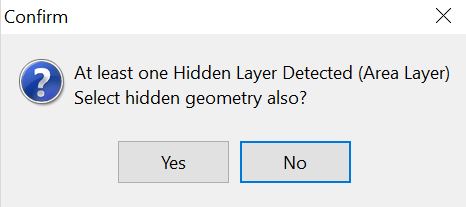
16Click No.
17Click the Processing tab to open the Processing Editor.
18Click Process All. Set the settings as shown:
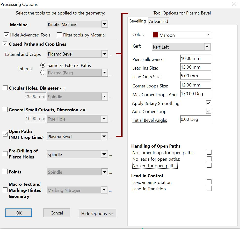
Importantly:
▪Lead Ins Size: 15mm
▪Lead Outs Size: 5mm
▪All Handling of Open Paths boxes are unchecked
▪Corner Loops Size: 12mm
▪Initial Bevel Angle: 0.00 Deg
19Click OK.
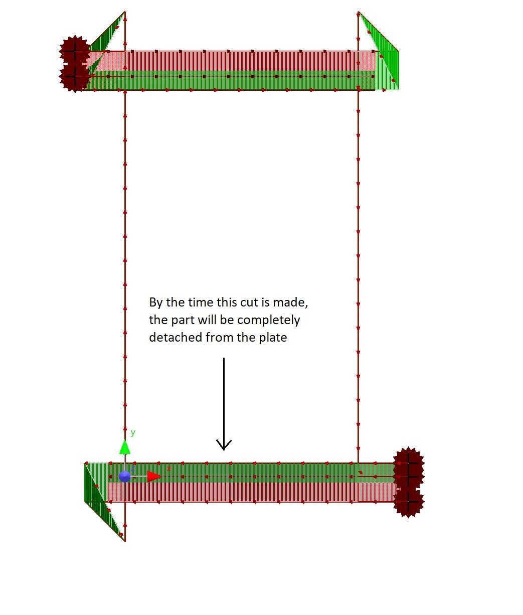
The final cut always must cut through a connection to the plate, so we must move the leadin of the last cut so that the final cut occurs on one of the vertical sides. This will cause the plate to detach on a non-critical straight cut rather than during a bevel cut.
20Select the Place Leads tool
21Click in the top left corner to move the lead.
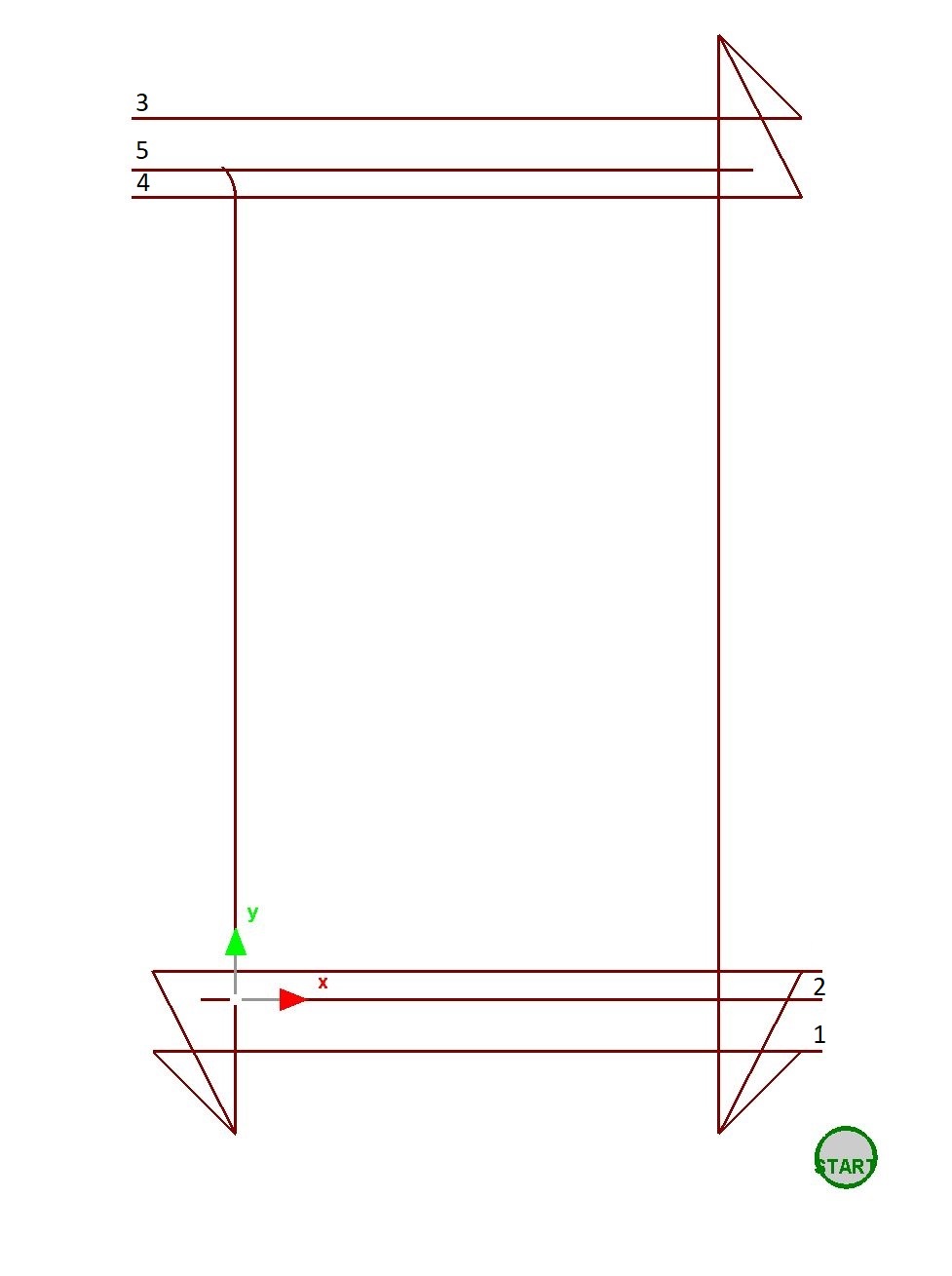
Now we need to sequence the part so that the cuts will be executed in the following order.
22Click on the Sequencing tab.
23Click on the Show button, select Show Sequence Numbers from context window.
This will show the order of operations in the part window, and as you click on a process in this window the same one will be highlighted in the list.
24Drag the processes in the list so that they occur in the order shown below.
This part could now be nested on a plate for processing. Remember that the part should NOT be reprocessed on the plate, and the plate should be sequenced on a part by part basis.