See also Pad Milling from 3D STEP Import
Available in Release 131
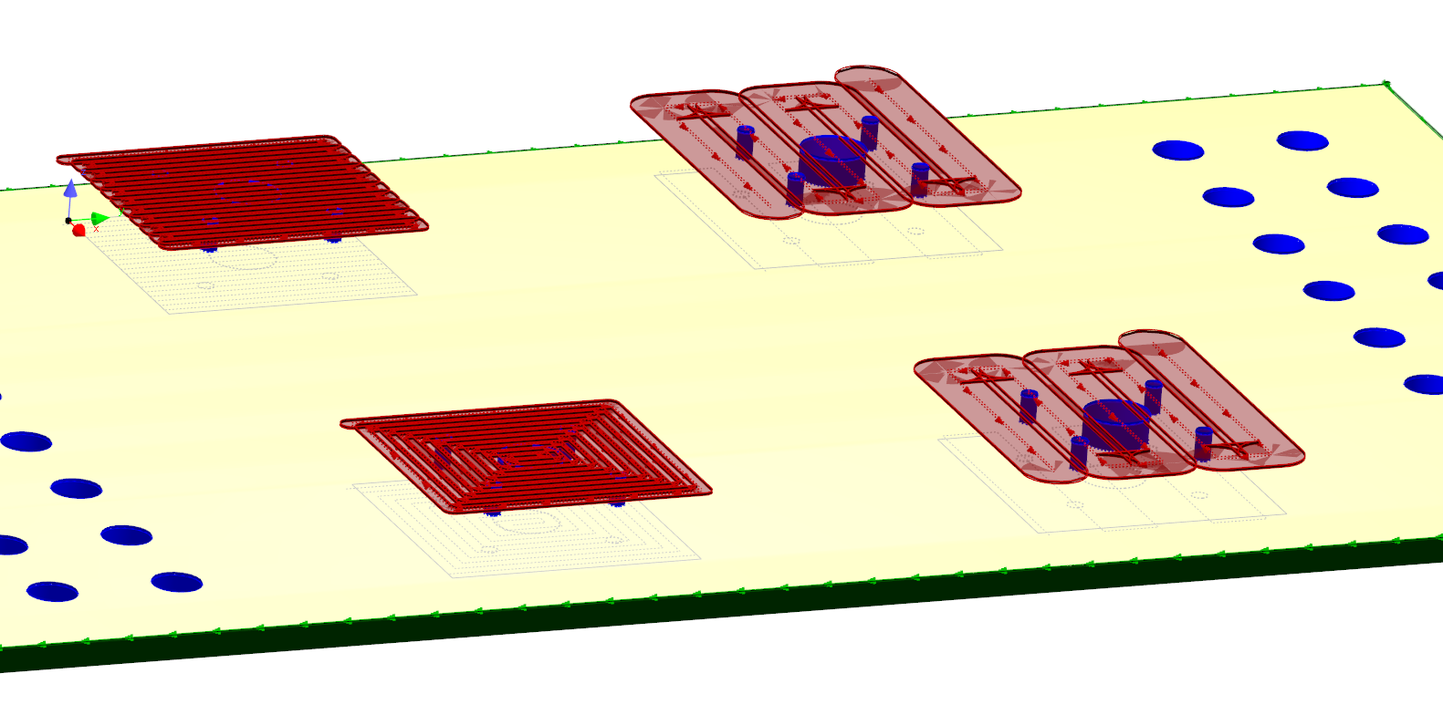
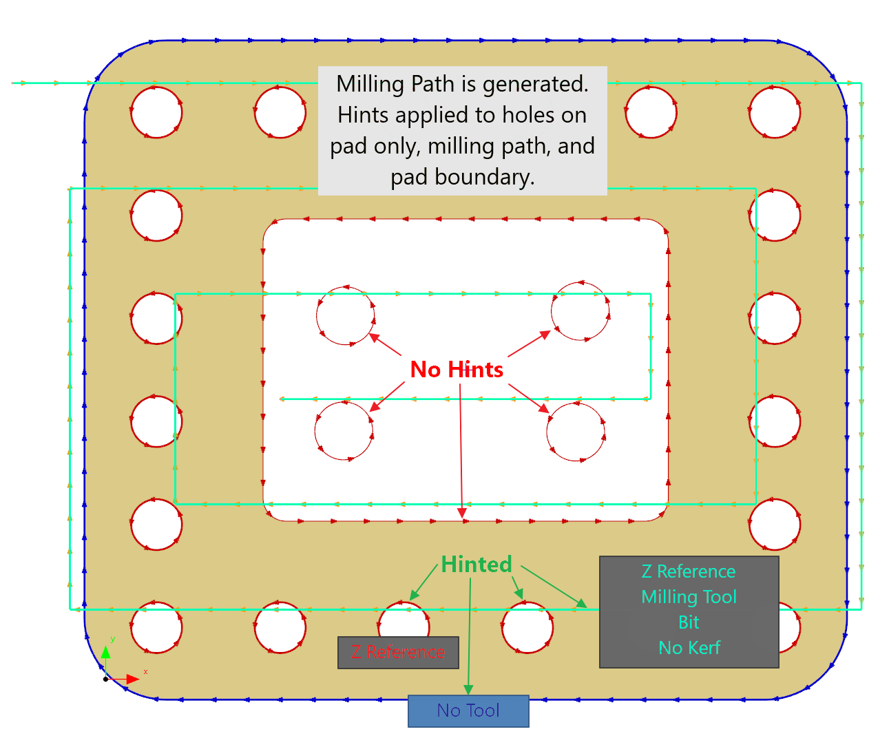
PrimeCut can create pad milling paths in the Part Geometry Editor, ie paths a facemill can traverse to machine the top surface of "pads". In doing so it will hint the milling geometry created with the bit to use, to use no-kerf, and to set a Z Reference at the pad height. Additionally it will hint any holes within the pad with the same Z reference so they also will be drilled in the same plane. No-Tool Hints are applied to the pad boundary path, so that it will not be processed. If it was already processed, perhaps the side of the pad are to be milled as well, then the processing will remain, and if you do want to apply processing to the side of the pad later, you must simply delete the No Tool hints via geometry editor properties when the pad boundaries are selected.
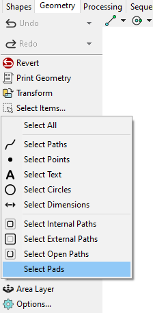
1.Select the path that represents the shape of the pad or multiple pads. You must select only Closed External paths defining the pad boundaries for this, so that it can properly recognize contained holes. It will not function if other geometry, eg text or holes, are selected.
A new Select Pads function has been added to make this easier
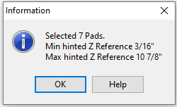
This will also tell you the Z Reference of the highest and lowest pads to inform you of whether A Z Reference offset is needed when applying the pad milling
2.Right click and select Apply Pad Milling alternatively Ctrl + Alt + P will also open the pad milling dialog shown below.
3.Click OK when ready, and the milling geometry will be created.

Pad Milling Dialog
The dialog options are:
•Pad height (Z Ref) / Offset Hinted ZRef By - The finished height of the pad. The milling path and contained holes will be hinted with this Z Ref so that when they are processed they will be automatically moved to the correct plane. If the Path geometry selected already has a Z-Reference hint, as happens when pads are imported from a 3D STEP file or similar, then this height is applied as an offset to the hinted height, and the caption will change to Offset Hinted ZRef By (ie: set to 0 to use the hinted ZRef heights)
•Milling Bit - The Mill bit for the current controller to use. The milling path is hinted with this bit name, and this also determines the diameter
•Bit Diameter - If a Milling Bit is selected, this will set the diameter used for spacing the milling paths. If no milling bits are set, or the part's controller is unassigned, then the diameter can be entered here manually.
•Overlap Distance - How much each successive mill path should overlap each other
•Pattern:
oOne Way - Individual Cuts are all parallel in the same direction
oZigZag - Cuts in both directions as a continuous path
oSquare Spiral - Cuts around the outside first then continues to the center as a single path
oNested Squares - A closed rectangular path is cut around the perimeter, followed by reducing closed cut paths to the center. Not recommended as it requires the mill to plunge onto the pad, unless leadins are manually added in processing
•Orientation - The orientation of the milling pattern
•Overlap Pad Edges - How much the milling path will overlap the edges of the pads (approximately)
•Fillet Corners - set to have the square corners filleted with a radius of the stepover
On-Pad Hole Handling
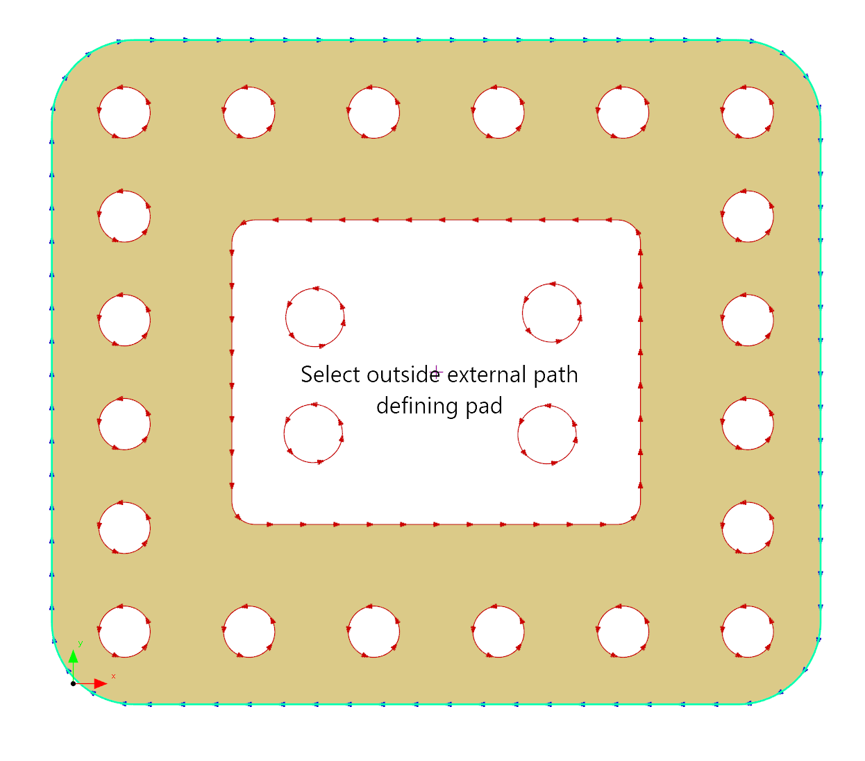
When generating the pad milling geometry, this function also applies ZRef hints (see below) to drillable holes within the pad, so called On-Pad Holes. It expects the outside of the pad to be selected, and drawn as a closed external path (clockwise in orientation) and will include all holes between the external contour and any contours within the selection. Holes with internal contours are therefore excluded.
Hints
Milling geometry created by the Pad Milling has processing hints automatically applied. Any existing hint of the same type is deleted/overwritten:
•Tool Hint: Milling, a milling tool will be applied. If the controller has a single milling tool, or a default milling tool, this will be the hint used.
•Bit Hint: If the milling bit was specified, this bit will be hinted so the milling tool will use it.
•Z-Reference Hint: Sets the Z-Reference on the created process to the Pad Height. See Local Coordinate Systems. This effectively sets a reference height for the mill to mill down to.
•Kerf Hint: The milling process should have no kerf, ie the mill center line will follow the geometry