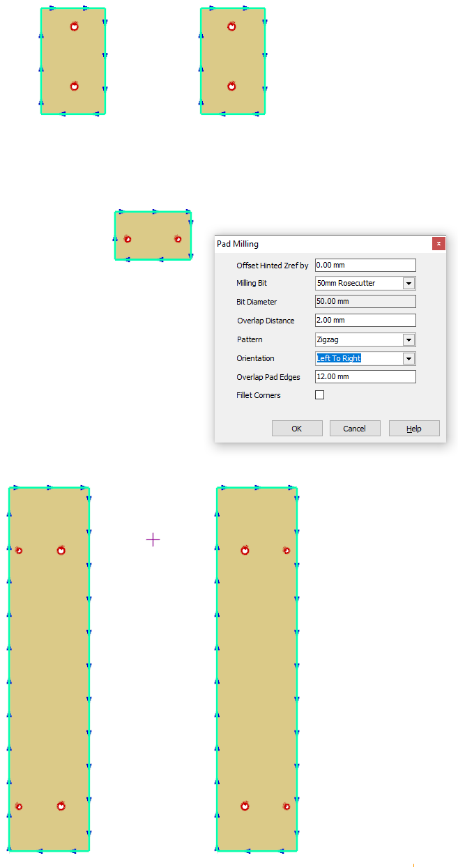
See also Pad Milling Path Creation
To simplify creation of Pad Milling geometry and heights, pads can be loaded from a STEP file, and the pads selected, as described in the procedure below. This function imports the pad boundaries and hints them with Z Reference hints so that processing can make use of them. Holes to be drilled within the pads also have Z Reference hoits applied.
First select STEP file as the file type to load:
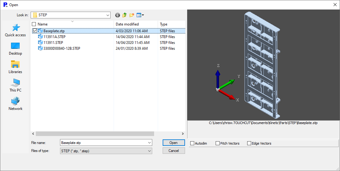
A preview is displayed in the "as-drawn" coordinate system.
After pressing Open the files is loaded into the Solid Model Container window. It will be reoriented so its shortest axis extent is aligned with the Z axis. Normally this window is used to load complete parts via the Import Part button, but the geometry here is too complex for this to process automatically, as it does not represent a flattened profile part, but more of an assembly of parts.
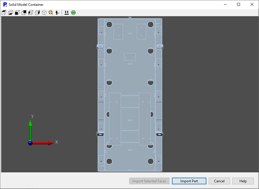
Solid Model Container
Next click on the ![]() (Set Top View) button. You may now select in sequence each face that is to be pad milled. Selecting a face twice removes it from the selection. The faces will remain highlighted after they are selected. be careful selecting the face, it is easy to mistakenly select some geometry on another plane. If geometry on anothert plane is selected, it will empty the current selection of faces, and rotate the model so that the surface normal of the last selected face is aligned with the Z Axis. You can use Alt-Right Drag to rotate the model view in space, if the faces you want to mill are not well presented.
(Set Top View) button. You may now select in sequence each face that is to be pad milled. Selecting a face twice removes it from the selection. The faces will remain highlighted after they are selected. be careful selecting the face, it is easy to mistakenly select some geometry on another plane. If geometry on anothert plane is selected, it will empty the current selection of faces, and rotate the model so that the surface normal of the last selected face is aligned with the Z Axis. You can use Alt-Right Drag to rotate the model view in space, if the faces you want to mill are not well presented.
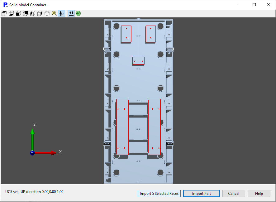
5 faces selected, shown with ray-tracing (shadows) enabled.
Finally Click Import n Selected Faces to load the profiles into PrimeCut. The pad boundaries as well as enclosed holes are loaded as Z reference hinted 2D geometry, ready to have Pad Milling applied. The Z Reference applied will be relative to the "lowest" point on the 3D model; this can be offset when applying the pad milling via the pad milling dialog Offset Z setting. In the example above, if the fabrication shown was to be bolted down to a machining table, You would set your Z reference in Touchcut on the machine to the top of the machining table, which is the same as the bottom of the assembly. You can select the pad boundaries in the geometry editor using the Select Pads function from the Select... menu on the toolbar. This will also confirm via a dialog the Z reference hints of the highest and lowest pads, so you can confirm they are correct or if not calculate a ZReference offset to enter into Offset Hinted Zref by below: