In this section we will use parts from the shapes library and apply basic processing, using flame to cut most of the geometry, and the spindle to drill the two smaller holes. The drill will also be used to create a pre-pierce hole, making it easier for the flame to start cutting. A tool has been set up in the controller for this purpose.
1Open the workorders mode.
2Search for and Open the workorder with the invoice number Part Processing.
3Double-click on the Flange 3 part in the parts explorer on the left.
4Click on the Processing tab in the editor. The part is displayed gray because there is currently no processing applied to it.
5Click the Process All button to apply processing.
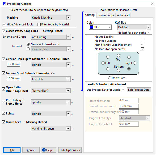
6Make the selections shown below and press the OK button.
Basic processing has now been applied to the part geometry:
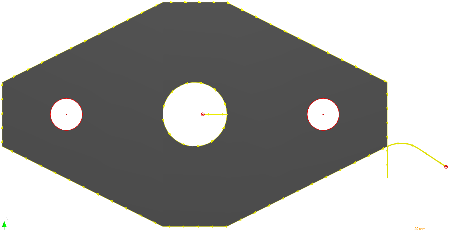
You will notice a number of points:
▪The smaller holes on the flange do not have arrows on their circumference, this indicates that they are being drilled and not cut. This is because on the processing options dialog we chose to apply the spindle to holes of 10mm or less.
▪Two holes have appeared at the start of the flame cutting paths, these are the spindle piercing holes we have used to pierce the material before using the flame. This has been done because on the processing options dialog we ticked the Pre-drilling of Pierce Holes check box.
▪The circle leadin is straight. This is due to the geometry of the part rather than any selection we have made. PrimeCut will place leads at corners where possible, as shown above. In the case of the large circle the cut starts at its center because the leadin length (20mm) is larger than the radius of the circle (10mm).
▪The color of the cut paths is yellow and drilled holes is red. This is our default setting for the display colors of our tools.
Perhaps we have now decided that the large hole should be drilled rather than cut with flame. We have two options to do this, either we process the entire part again, or we select only the geometry concerned and apply processing to that. In this case we will process the whole part again, but if the part was more complex it may be preferable to select the hole on its own.
7Click the Process button. Since the part is already completely processed, you will be presented with a dialog asking you to confirm that you want to re-process it, Click the Yes button.
8On the Processing Options dialog change the Circular Holes up to Diameter field from 10mm to 20mm.

9 Click the OK button to re-process the part.
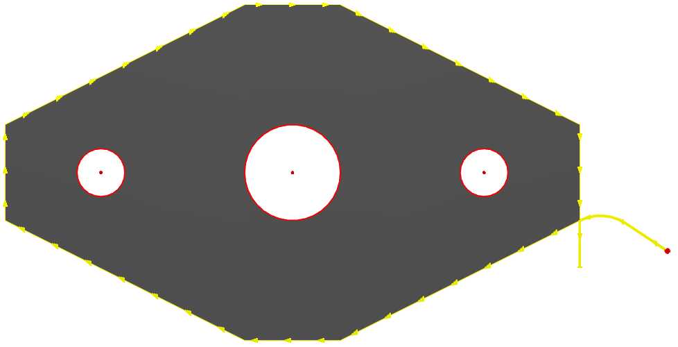
You can see that the large hole is now being drilled and not cut with flame.
Suppose that (for some reason) the integrity of the sides of the flange is much more important than that of the top and bottom. PrimeCut has decided to place the leadin on the 'sharpest' corner, but we want to override this automatic decision and move to somewhere more suitable. There are two methods we could use to achieve this.
By selecting the process itself (not the leads) we will be presented with handles that allow us to manually move the leads.
10Use a crossing rectangle (from right to left) to select the external path of the part (NOT the leadin/leadout). Make sure you don't cross any of the holes; otherwise the handle will not be displayed.
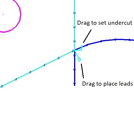
Notice the handles that have appeared at the start point. The lower handle allows us to place the leads (and in doing so our start point), while the handle above allows us to set undercut. Undercut will be discussed in the next example.
11Click on the 'place leads' handle (don't hold the mouse button down, just Click and release). You can now move the mouse around the part and the lead placement will follow. The placement will snap to the corners when you get close to them.
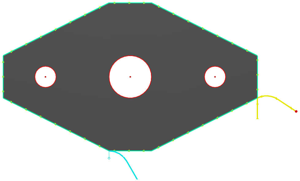
12Drag the handle to the bottom of the part as shown below and Click again to place the leads at that location.
Alternatively the 'Place Leads' button lets us Click on the area of the part where we would like the leads (which are located at the start point) to appear.
13Click the Place Leads ![]() button on the processing editor sidebar:
button on the processing editor sidebar:
The mouse pointer will change to a square, and a tick will appear when you are over a valid location. If you place the leads close to a corner, they will snap to that corner.
14Place the pointer over one of the corners at the top of the part and Click the mouse to place the leads there.
15If you are stopping here, close the mode without saving, or else skip to step 3 in the next tutorial.