One reason for using a leadin is that the piercing hole may be irregular, and therefore should be away from the part being cut. The second reason is that a significant amount of dross can be created when piercing, and a leadin prevents the cutting tool from running into this and being damaged.
A leadout is used primarily to ensure a cut is finished cleanly. Other than this it is occasionally used to prevent damage caused by a 'drop' (small part) pivoting on a slat and hitting the torch, but this is of concern only for very small parts that may be unsupported when cut.
Undercut is the practice of finishing a cut early, and may result in the part staying attached to the plate. This can be used to prevent blowout, which can be caused by the tool path crossing itself. It may be used in combination with a leadout.
As was apparent in the last example, PrimeCut will attempt to place the start of a path at a corner, and in such situations the leadin will be a straight line. In this example the part we are cutting is circular, and so there is no corner to start on. In this situation PrimeCut will use a tangential arc as a leadin, so that the transition is as smooth as possible. Alternatively, in the case of a small hole, a straight radial lead will be used.
1Open the Workorders mode from the start screen.
2Search for the workorder with Part Processing as it's invoice number. Click on it and Click View.
3Double-click on the Processing Flange part in the parts explorer.
4Click on the Processing tab at the top of the screen.
5Click the Process All button to display the processing options dialog.
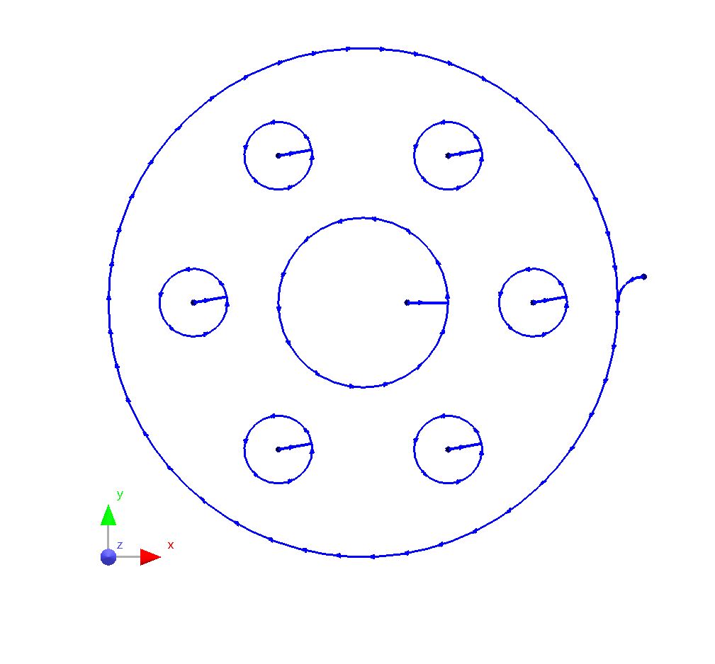
We want to cut this part entirely using plasma, including all of the holes.
6Make the selections shown below and press the OK button to apply the processing.
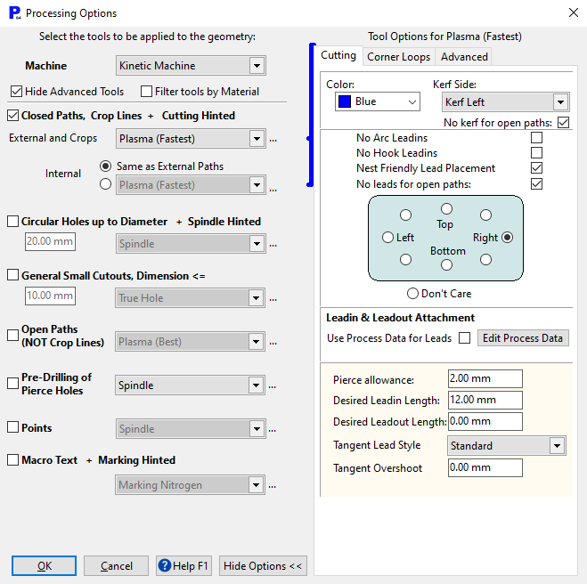
Click the ... button ![]() under Closed Paths, External, to see the full options.
under Closed Paths, External, to see the full options.
To match our pictures, choose
▪Plasma(Fastest)
▪Leadin Length: 12.00mm
▪Leadout Length: 0.00mm
▪Right radio button for lead placement.
▪Set the color to blue
Now suppose that we are concerned about the possibility of blowout (where material is removed from the part itself) caused by the tool path crossing itself, and we wish to introduce undercut so the cut finishes before this happens. There are two methods we can use to achieve this.
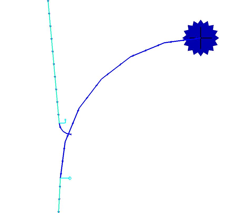
In the last example we used the 'place leads' handle to move the start point of the cut. The other handle we saw (with the smaller diamond shape) is used to set the undercut.
7Zoom in on the start point to give a better view.
8Use a crossing rectangle (from right to left) to select the outside cutting path. Once again, do not select the leadin itself or any other paths.
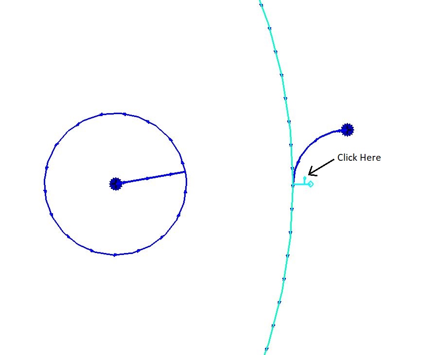
9Click on the undercut handle and release the mouse button. Dragging the handle will now move the end point of the cut.
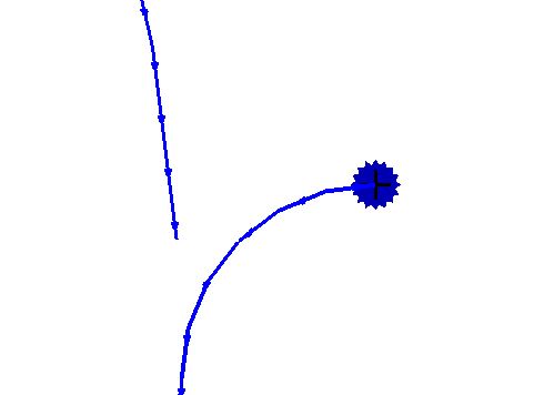
10Drag the handle to a position similar to that shown below and Click the mouse to place the end point.

As you can see the cut now finishes before it reaches the leadin.
The second method is to set the undercut using the properties dialog.
11As before, use a crossing rectangle to select the outside cutting path. The properties for the path will be shown.
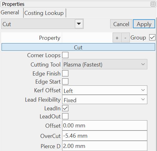
In this case you can see that the current undercut is 5.46mm, although it is shown as an overcut with negative value.
12Change the overcut value to -2.5, and Click the Apply button. The undercut has been changed to 2.5mm.
With the current processing, the part may end up attached to the plate. If the undercut is small then it may simply be a matter of snapping the part from the plate. Alternatively we can use a leadout to close the cutting path and guarantee complete severance of part from the plate.
13Once again, select the outside cutting path to show the properties for the path.
14On the properties dialog tick the LeadOut checkbox and Click the Apply button. The path now has a leadout that crosses the leadin.
The chance of blowout is now minimized, and a small amount of finishing will be required to remove the 'nipple' resulting from the undercut.
You can see that the leadout is quite short in this case. Perhaps we wish to lengthen it so that it is a similar size to the leadin.
15Once again, use a crossing rectangle to select the outside path.
16Right-click to display the popup context menu and Click on Select LeadOut.
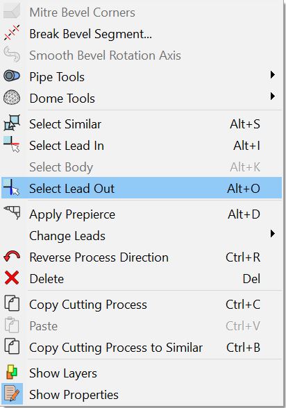
The properties for the leadout are now displayed.
17Change the Leadout Length value to 8mm and Leadout Radius to 4mm. Click the Apply button. The leadout is now the same size as the leadin.
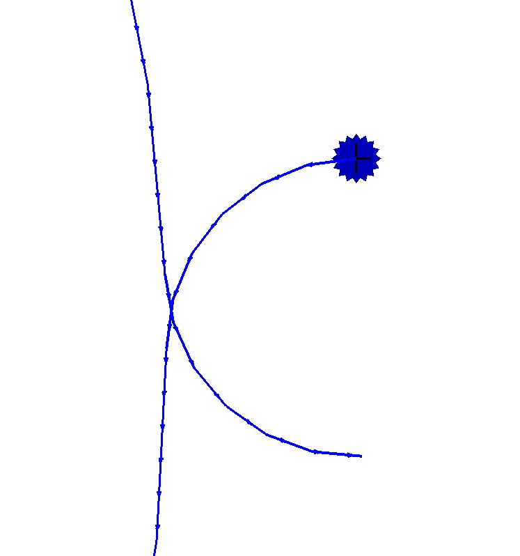
This has reduced the size of the resulting 'nipple', and it may be necessary to increase the undercut as a consequence. This would be done in the same way as before.
18Close the mode without saving.