1Open the Milling Tutorials Invoice Number workorder from the workorders mode. Open the MillRoughMillFinish part from the parts explorer.
2Click on the Geometry tab to open it in the Geometry editor, then click on the Processing editor tab.
3Press the Process All button to display the Processing Options dialog and use the settings shown below.
We will use the milling bit to perform the roughing cut, then after the operator has removed the resulting blank we will clean up the face of the cut using an end mill bit.
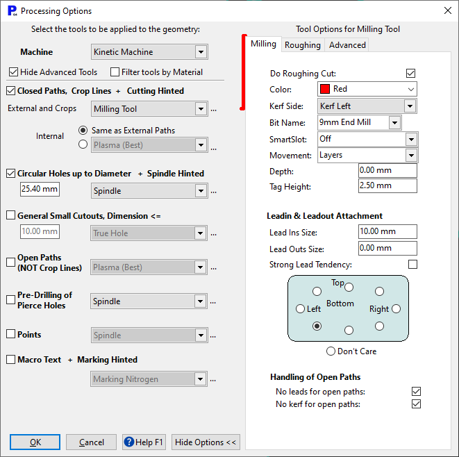
The following settings are important in this case:
▪Select the 9mm End Mill bit from the Bit Name drop down menu.
▪Specify a 'sensible' value for the Tag Height; in this case 2.5mm but you will determine the most appropriate tag height for your own parts through testing at the machine. Tags need to be used in this case because we are milling the outside path. If they were not used then the part would be severed from the plate by the roughing cuts, and would be unsecured for the finishing cut. The result would be a broken milling bit at best, and more severe damage to the machine at worst.
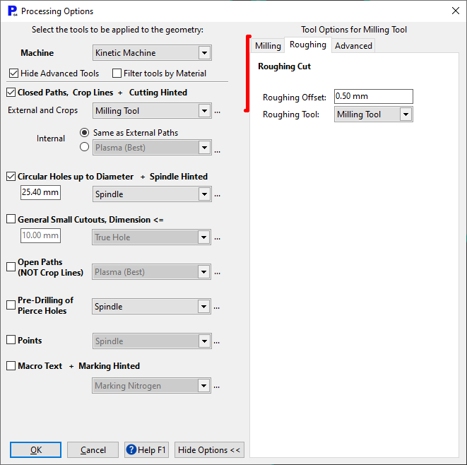
▪Tick the Do Roughing Cut check box in the Milling tab
▪Specifying a small Roughing Offset. Because we are using a milling bit for the roughing pass, and the result will be tidier than plasma, we can us a smaller offset.
▪Specify Milling Tool for the Roughing Tool.
▪Press OK. Press OK to dismiss the Spindle Processor window if it appears (the holes are not relevant to this tutorial).
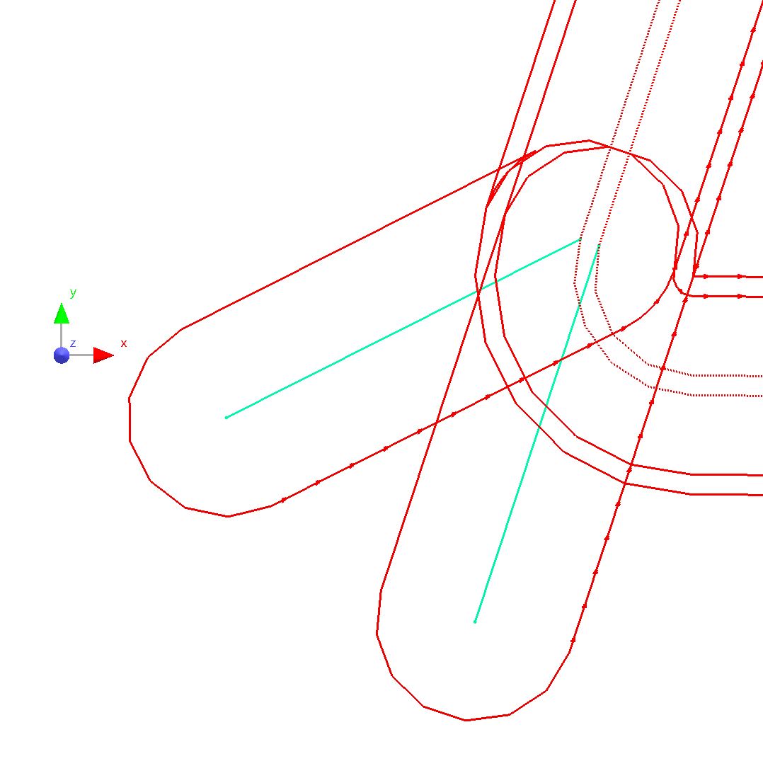
You will see that in this case we have two milling paths, one for the roughing and one for the finishing. If you want to move the leads it makes sense to not place them in the same location, and the easiest way to do this is by using the Place Leads button. In this case we are going to leave the leads where they are but change them to "hook" leads and make them longer to allow for the ramping of the bit. A hook lead is used because the ramp will occur over the first path segment, and this means that the ramp is completed at the beginning of the radius segment of the lead, ensuring the bit is already at the right height when the cut path is reached.
4Draw an enclosing rectangle (left to right) around the leads to select them and view their properties. You will be selecting the leads for both the roughing pass and the finishing path, so any changes made will affect both.
5In the properties dialog change the Leadin Type to Hook and press the Apply button.
6Select the leads again to view and modify the properties.
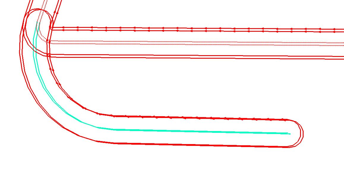
▪Change Leadin Length to 60mm to give extra distance for the ramping.
▪Change Leadin Radius to 15mm to shift it away from the path.
▪Change Leadin Angle to 0 to make it tangential to the path.
▪Change Leadin Swept Angle to -107 degrees from to minimize the 'footprint' of the processed part.
Finally we need to put in some tags to keep the part secured while it is being processed. The part can then be ground, or digitrimmed from the plate later.
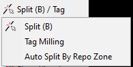
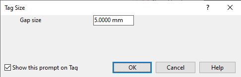
7Press the Split / Tag > Tag Milling button and enter an appropriate tag size into the dialog that appears.
You need to add tags to both the Roughing and the Finishing milling passes. To do this you will need to zoom in on the area where you would like to place the tag. When you do this you will see two separate dotted lines, one for each pass.
8Drag the mouse over the paths and they will change color separately to show they are selected. Click to place a tag on one path, then move to the other and place a tag in the same location on that path.
9You should put the tags in three locations around the part to ensure it is held securely.
You can now nest the part on a plate as you would with any other pre-processed part.