Where the machine is fitted with some sort of tool changer (including turret drills) the spindle table is used to control which tools are selected to be used on different holes in the program. It also allows you to apply sequences of tool operations to each hole making it easy, for example, to have a drilling process followed by a tapping process.
Each operation applied is called a Spindle Operation, and a group of these Spindle Operations to be applied to a hole size is called a Spindle Sequence.
The order of the operations within a sequence defines the order in which they will be applied, and applies constraints to the sequence optimizer. It does not mean in our drill/tap example that each hole will be drilled and tapped immediately afterward, but it does mean that none of these holes will be tapped until they have first been drilled.
It then puts the appropriate tool names into the NC code so that the correct tools will be loaded into the spindle. It is critical that the names in the table match the names being used at the machine, otherwise the correct tool will not be selected.
When you click on the Edit Spindle Table button from the advanced options when processing or the Spindles button in the Machines mode , the following window will be displayed (this shows the windows being displayed from the Processing Options dialog):
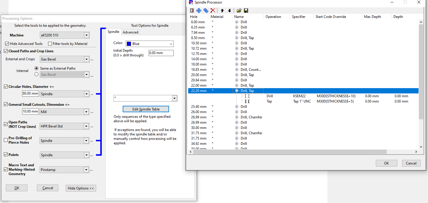
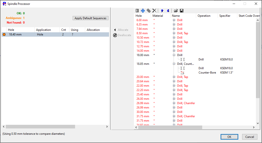
The entries in the table represent hole sizes that PrimeCut NE can process. There can be more than one set of entries (Spindle Sequences) for any given hole diameter, allowing you to select the preferred application as you apply processing, or select it using the spindle application filter (the drop down box just above the Edit Spindle Table Button).
NOTE Spindle Operations defined here can use any Tool Specifier as its just a string. This is generally all that is needed to generate a program for the machine. If you want to know how long this operation will take for quoting or planning, then you also need to add spindle costing information via Spindle Costing Data.
Double-clicking a Spindle Sequence row will show this:
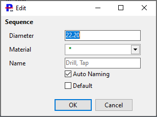
Hole / Diameter
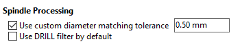
The diameter of the hole to match against. PrimeCut will apply a toleranced match and this tolerance can be controlled in User Options, Processing Tab:
Material
We can further restrict the application of a Spindle Sequence to only apply to a certain Grade of material. Usually however this is simply "*",matching any material.
Name
The name of the Spindle Sequence. A unique list of these names is compiled as options for the spindle application filter as well as * meaning all Spindle Sequences. The name can be automatically generated (Auto Name checked) from the basic descriptions of the Spindle Operations it comprises, or it can be given a custom name by the programmer.
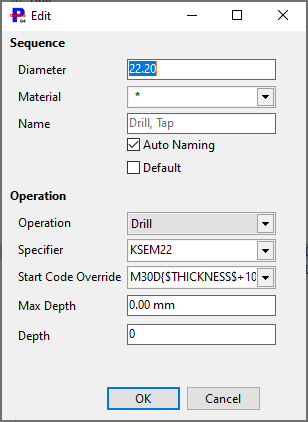
Operation
Lists the basic types of Spindle Operation: Drill, Tap, Pre-Drill, Chamfer, Countersink, Bore. The choice of type may affect how the operation is rendered in the graphics windows, as well as how costing calculations are performed (for example taps and boring tools feed into and out of holes, while other operations feed in and rapid out)
The tool Specifier (bit name) to be used. Must match the names of the tools on the machine for Touchcut controllers.
Start Code Override
Some tools may have their normal start codes overriden here. This is particularly true of chamfer tools where chamfer macros are likely to be used, but also perhaps for drilling and tapping where the drill may be forced to drill deeper than the tap, to prevent the tap bottoming out and jamming on a slat or pin.
Max Depth
Some tools may have a maximum depth of material to which they can be applied; this is a safety check to prevent tools being applied to too great a depth.
Depth
Similar to Start Code Override above, however this only overrides the depth traveled to. Expressions involving Thickness, Drawn diameter and Tool diameter can be used here, for example "thickness+5" will drill to a depth 5mm below the bottom of the material (if mm setting are in effect, if using inches this will drill 5" below the plate!).
See Using Formulas for Depth for a more detailed description, and Controlling Spindle Depth for a more general discussion of spindle depth.
The spindle allocation table may pop up dynamically when processing holes under the following circumstances:
•Holes with diameters not matching (within the spindle matching tolerance) those in the spindle table were found
•Matching diameters exist, but the spindle application filter prevents matches being found (eg filter is set to DRILL, and there is only an entry for Drill, Tap)
•Matching diameters exist, but the Material Filter on the spindle Sequences is incompatible.
•There is more than one match creating an ambiguous situation.
In this mode, selecting the unallocated holes on the left and then double-clicking a Spindle Sequence on the right will allocate the sequence to the hole type. You can also use the Allocate (and Unallocate) buttons, and add new Spindle Sequences and Spindle Operations on the fly here .