In this tutorial we will process a filleted triangle starting with a bevel angle of zero degrees, working up to 45º, and then finishing back at zero degrees.
1Open the Parts mode and click on New 2D Shape ![]() .
.
2Load the Filleted Triangle part from the Shapes Wizard.
3Set the fillet radius as 10mm and change all of the side lengths to 150mm (5.91"). Click Finish.
4In the Properties tab open the Material/Thickness dropdown and select Mild Steel, 20.00 mm.
5Click on the Processing Editor tab to open the part in that editor, and press the Process All button.
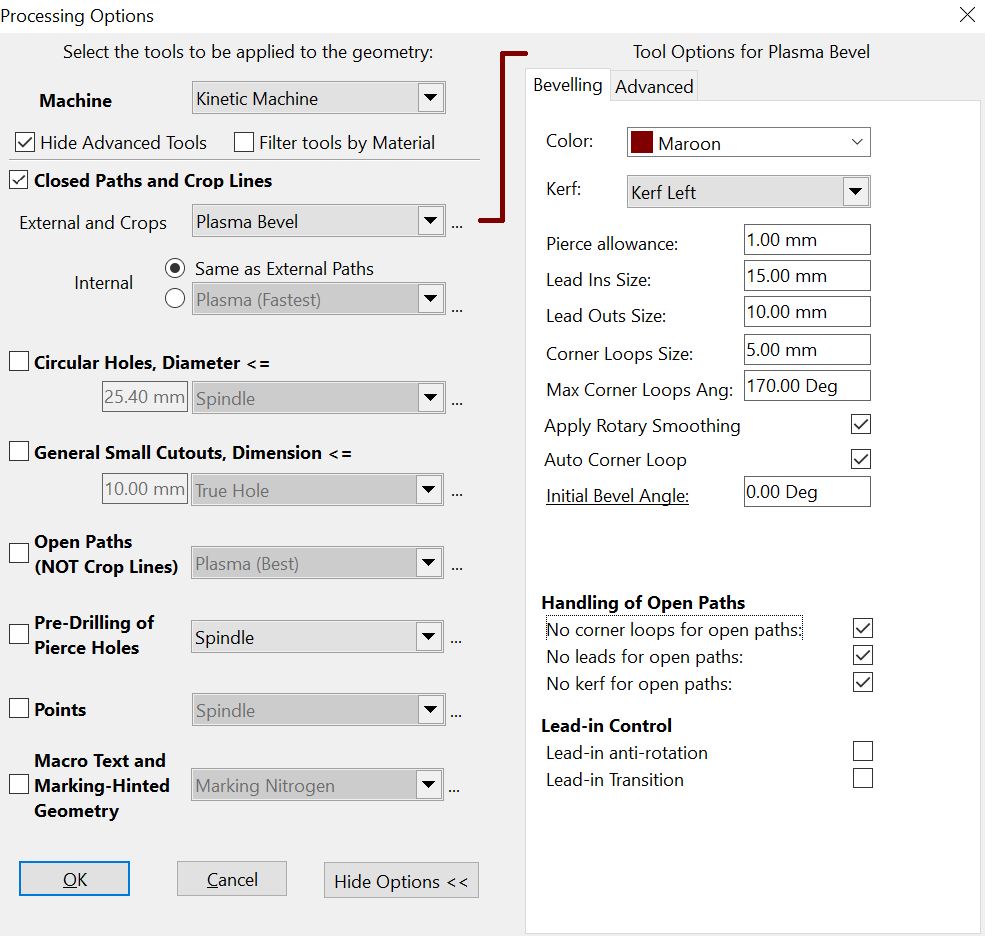
▪Tick Closed Paths
▪Select the Plasma Bevel tool from the drop down menu.
▪Make sure the Initial Bevel Angle is set to zero degrees. The other parameters are not critical for the purposes of this tutorial.
6Click the OK button to perform the processing.
7Click Place Leads and click the path to place leads approximately as shown.
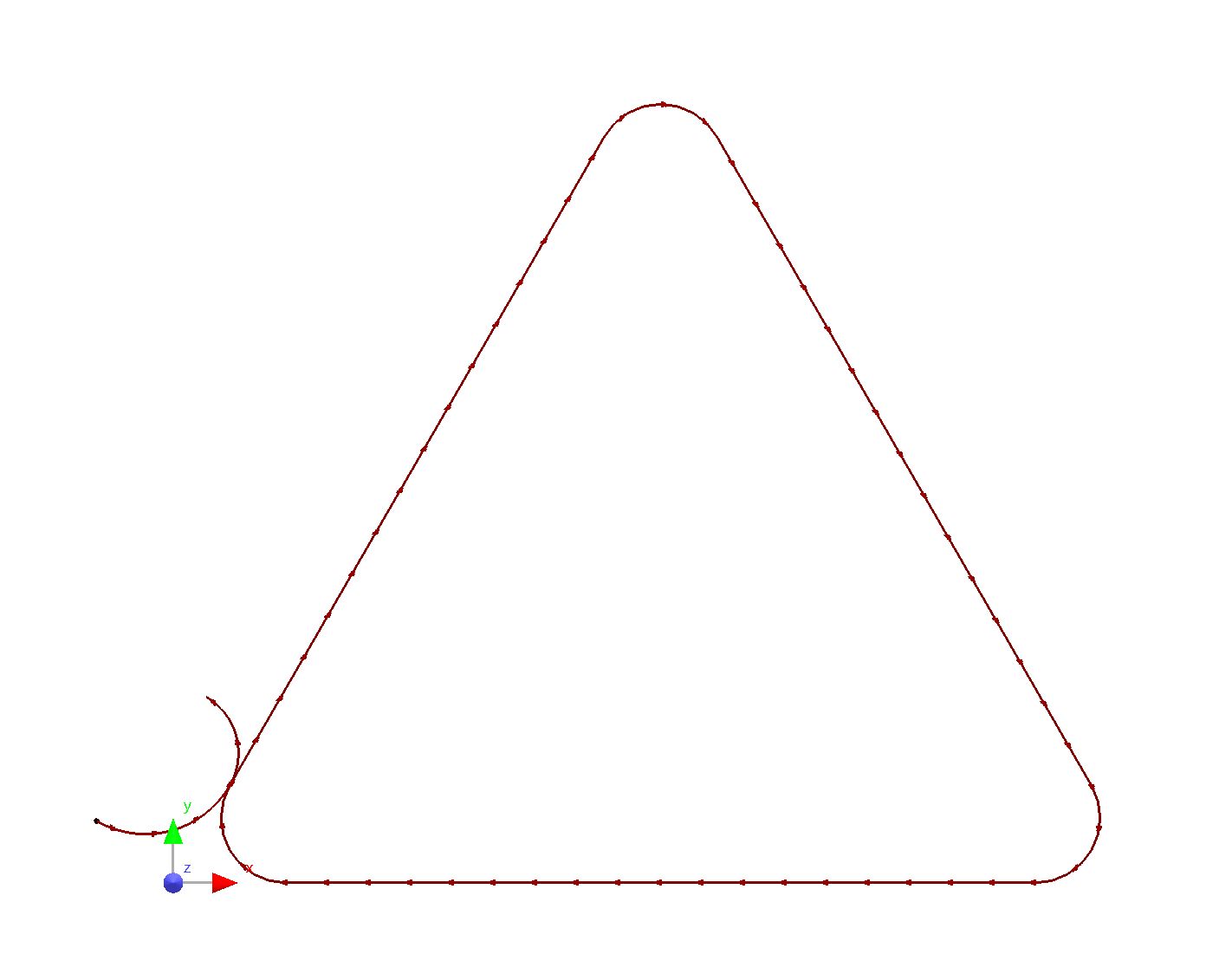
8Try selecting the cutting path, and you will notice that the fillets and sides are separated into individual segments. This allows us to change the characteristics of each independently.
9Select the right hand side of the triangle so that you can view its properties.
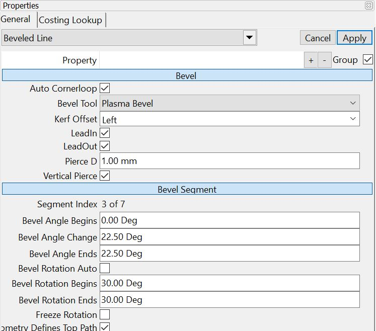
▪Change the Bevel Angle Change value to 45. The means the path will start with a zero bevel angle, increasing to 45º over the length of the path. You could change Bevel Angle Change parameter or Bevel Angle Ends, the effect will be the same.
Also, change the Geometry Defines: dropdown to top. If this is not done then the geometry will instead define the extents of the part. Be aware that the 'industry standard' is for the geometry to define the extents of the part, although you may have different standards within your organization. So generally you will leave it set to Extents. Click Apply button.
10Now select the bottom right hand corner to view its properties.
▪Change the Bevel Angle Begins value to 45º, but leave Bevel Angle Change as zero.
▪Change Geometry Defines: to Top. Click Apply button.
11Now select the bottom side of the triangle.
▪Change the Bevel Angle Begins value to 45º.
▪Enter -45 as the Bevel Angle Change value.
▪Once again change Geometry Defines: to Top. Click Apply button.
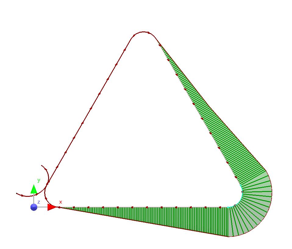
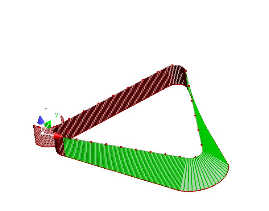
You can now view the geometry we have created in 3D, so you can confirm that it is correct.
12Hold the ALT key, right-click on your mouse, and drag the mouse around the screen.
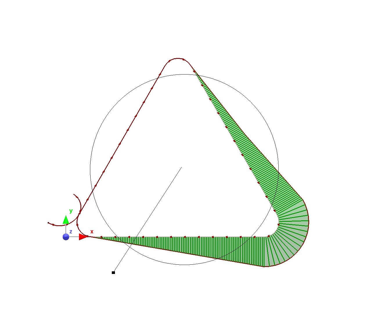
Dragging while the mouse pointer is inside the circle will rotate the part. If it is outside the circle the part will spin.