The example below shows a single segment selected on a bevel process. The Bevel Process Properties are shown grouped in Red, these apply to the entire Bevel Process.
The Bevel Segment Properties are grouped in Blue.
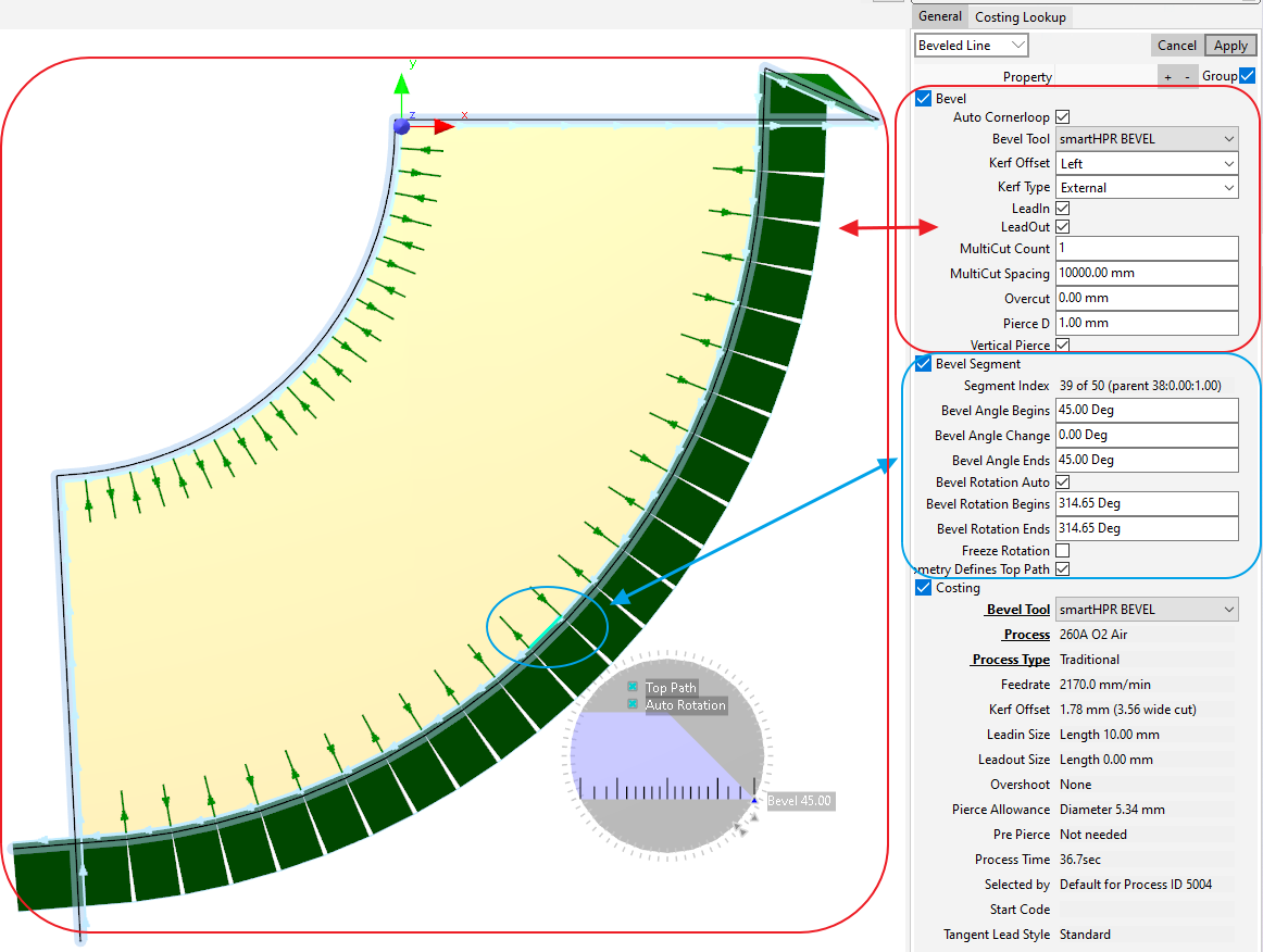
Most of these properties are similar to those for cutting processes, so we will only highlight here the bevel specific ones.
Auto Cornerloop If Checked PrimeCut will automatically add corner loops as required. Corner loop are required on any corners (that are not Mitered ) where there is a jump in either Bevel Angle or Bevel Rotation.
Vertical Pierce If the process is to start cutting at a bevel angle, the normal practice is to pierce vertically (ie Vertical Pierce checked) then lean the torch over to the starting angle, and usually this is done at the start of a leadin. The vertical pierce is easier on consumables and produces less of a shower of sparks and hot debris. Sometimes however we may need to Pierce at the starting bevel angle, for example when adding a bevel to the edge of a plate, where there is nowhere to leadin from.
These settings describe how the bevel behaves over this single segment.
Bevel Segment Index (Readonly) The segments are numbered from 1. If a single segment is selected this shows the position it is at. You can navigate the bevel segments with ALT-P (Previous Bevel Segment) and ALT-N (Next Bevel Segment)
Bevel Angle Begins, Bevel Angle Change, Bevel Angle Ends These control the torch "tilt angle" over the segment. A Tilt Angle of 0 defines a vertical cut. Most plasma tools will have limits as to their maximum tilt angle, typically 45, 50 or 70 degrees- you can set this under the bevel tool. If the Bevel Angle Begins and Bevel Angle Ends are opposite signs then the bevel angle will pass through 0, and on some bevels including the Kinetic bevel, this involves an implicit 180 degree azimuth rotation.
Obviously there is a relationship:
Bevel Angle Begins + Bevel Angle Change = Bevel Angle Ends
Bevel Rotation Auto, Bevel Rotation Begins, Bevel Rotation Ends These define how the bevel azimuth axis is oriented. If Auto is checked, the other two settings are automatically computer to keep the plane in which the torch is beveling perpendicular to the direction of travel, so that a torch angle of 45 degree will produce a cut face angle of 45 degrees. Some operations such as Mitering and Bevel Rotary Smoothing will deactivate Bevel Rotation Auto and pre-compute appropriate values for the Rotation Begins and Rotation Ends values.
Freeze Rotation Specifies that the azimuth axis will not move over this segment- normally only used on 3rd party bevels with do not support Explicit Azimuth Control, as the Kinetic Advanced Bevel does, some of these bevels support "following" and "fixed" only.
Geometry Defines Top Path This is a key property defining the shape and size of the finished part. For Zero and Negative bevel angles, where the bevel cuts under the part, it has no real effect. But when the bevel angle is positive it defines whether the geometry the bevel process was applied defines the top path of the cut, or the bottom edge of the positive knife bevel. See more info in Useful Information on Bevelling