In PrimeCut NE there is a processing action to Miter bevel corners. This attempts to join two bevel segments without a corner loop (outside corners) or bevel decoration (inside corners).
On external beveled corners, there may be little difference in the end result of cutting between corner loops and mitering of the corners when using plasma, so long as Maximum Bevel Angle is not exceeded (see below), however corner loops do occupy more plate, and may therefore use more material when nesting. On internal corners a corner loop is not applicable of course, and if flame cutting corner loops are problematic as the cut will usually go out trying to cross its own kerf.
Note that mitering bevel segments is applicable to linear segments only - arc's are not supported for miter bevels as the bevel rotation is already applied in keeping the bevel surface perpendicular to the cut direction.
A corner loop and bevel decoration segment - without mitered bevels are shown below.
Mitered Bevel Corners
To apply miter bevels:
1.Open a beveled part in the processing editor window.
2.Select all the geometry - or only the segments of the corners that you want miter bevels applied to
3.Right click to bring up the context menu.
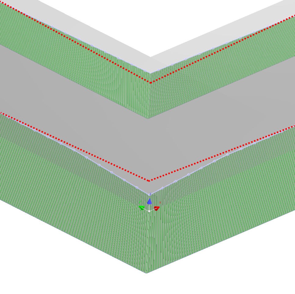
4.Select 'Miter bevel corners' from the menu and the corners will be mitered similar to the image shown below
Note that there are small transitional segments before and after the beveled corner to allow the change in bevel angle and direction to be gradually applied to meet the other bevel segment at the apex of the corner. Geometry Defines Top Path is supported however:
NOTE Mitered corners cannot be applied to corners where the intersecting bevel segments have different setting of Geometry Defines Top Path. Both segments must be the same in this regard.
Miter Bevel Segment Length
To apply miter to the bevels - the segments must be long enough to allow for the transition segment to be applied, very short segments will not be mitered. Normally this is based on the "width" of the bevel (for a 45 degree bevel, the "width" is the same as the material thickness, as the bevel angle decreases so does the width). On thin materials this can result in a very short, fast transition, and so a setting is provided:
The Miter Distance is defined as below. By default it will be twice the Bevel Width, but on thin materials or where the bevel angle is small, you may wish to make it longer; hence you can set a Miter Min Distance.
")
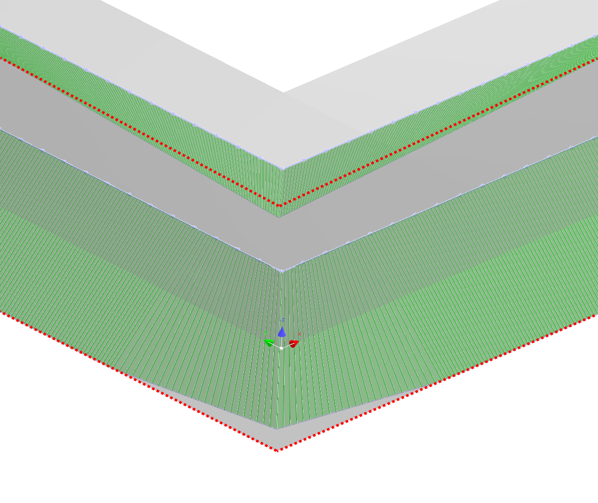
Miter Min Distance Example, viewed from above: 45 degree bevel on 20mm thick plate, Miter Min Distance here is set to 50mm. (Max bevel angle is 45 and Preserve Bottom Path was selected)
The compound angle at the apex of a mitered corner is greater than the segments going into, and out of a mitered corner. This causes a problem when the apex angle is greater than the Maximum Bevel Angle that the torch can accommodate. For example, a 90 degree corner with edges beveled at 45 degrees requires the torch to tip to approximately 53 degrees to achieve a perfect miter (easier to achieve with an XPR plasma or flame torch than an HPR plasma).
Note the Maximum Bevel Angle can be set in the machine settings (default of 45 degrees) shown below.
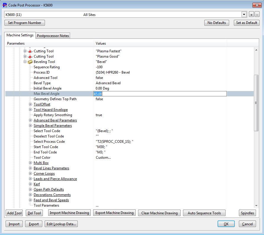
The maximum bevel angle is a property of the bevel tool and will depend on both your cutting systems' torch geometry and the Kinetic or other bevel unit. For example, Hypertherm XPR systems have a "pointy" torch and can bevel a little beyond53 degrees while HPR torch cannot go much beyond 45 degrees, and a flame torch's Max Bevel Angle is really only limited by how much extra preheat flame is required to preserve the cut quality. Kinetic Has bevel assemblies capable of just over 45 degrees, or up to 70 degrees. The Max Bevel Angle setting should be the minimum of the torch and bevel assembly physical limits.
Max Bevel Angle: What Happens when the Miter Bevel Angle is Too Big?
When the maximum bevel angle is exceeded, the miter bevels action can compensate for the bevel by preserving the top or bottom path. This will result in removing too much material from the part or leaving more material on the part as shown below
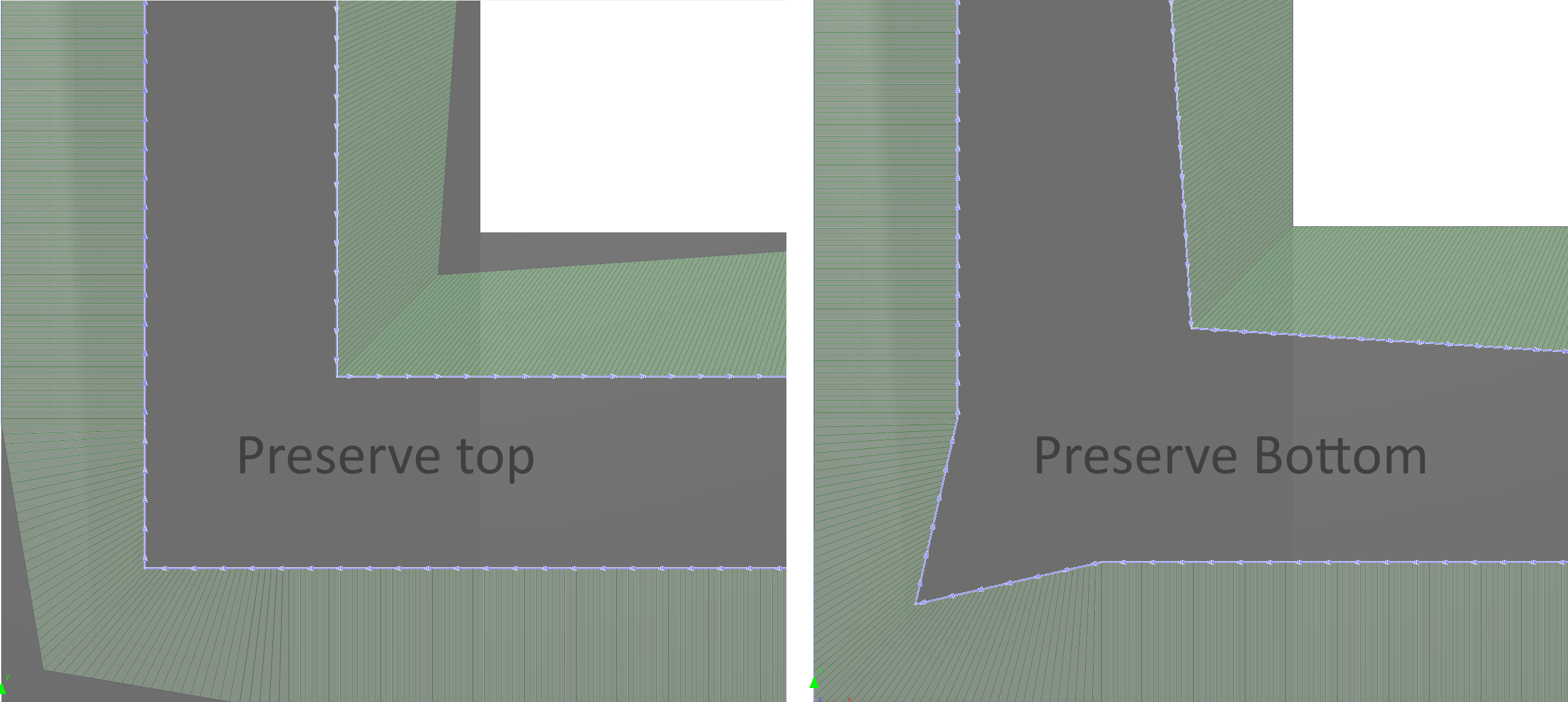
Exceeding Max Bevel Angle - Preserve Top
The 'internal' and 'external' corners below have exceeded the max bevel angle of the torch and the 'Preserve Top' option has been selected.
The top of the cutting path has kept its course and shape, the bottom paths are modified causing an overcut -removing extra material from the part, but still allowing the corners to be mitered.
Exceeding Max Bevel Angle - Preserve Bottom
The 'internal' and 'external' corners below have exceeded the max bevel angle of the torch and the 'Preserve Bottom' option has been selected.
The bottom of the cutting path has kept its course and shape, the top paths are modified causing an under -leaving extra material on the part, but still allowing the corners to be mitered. It should be easy to clean this corner up with a grinder.
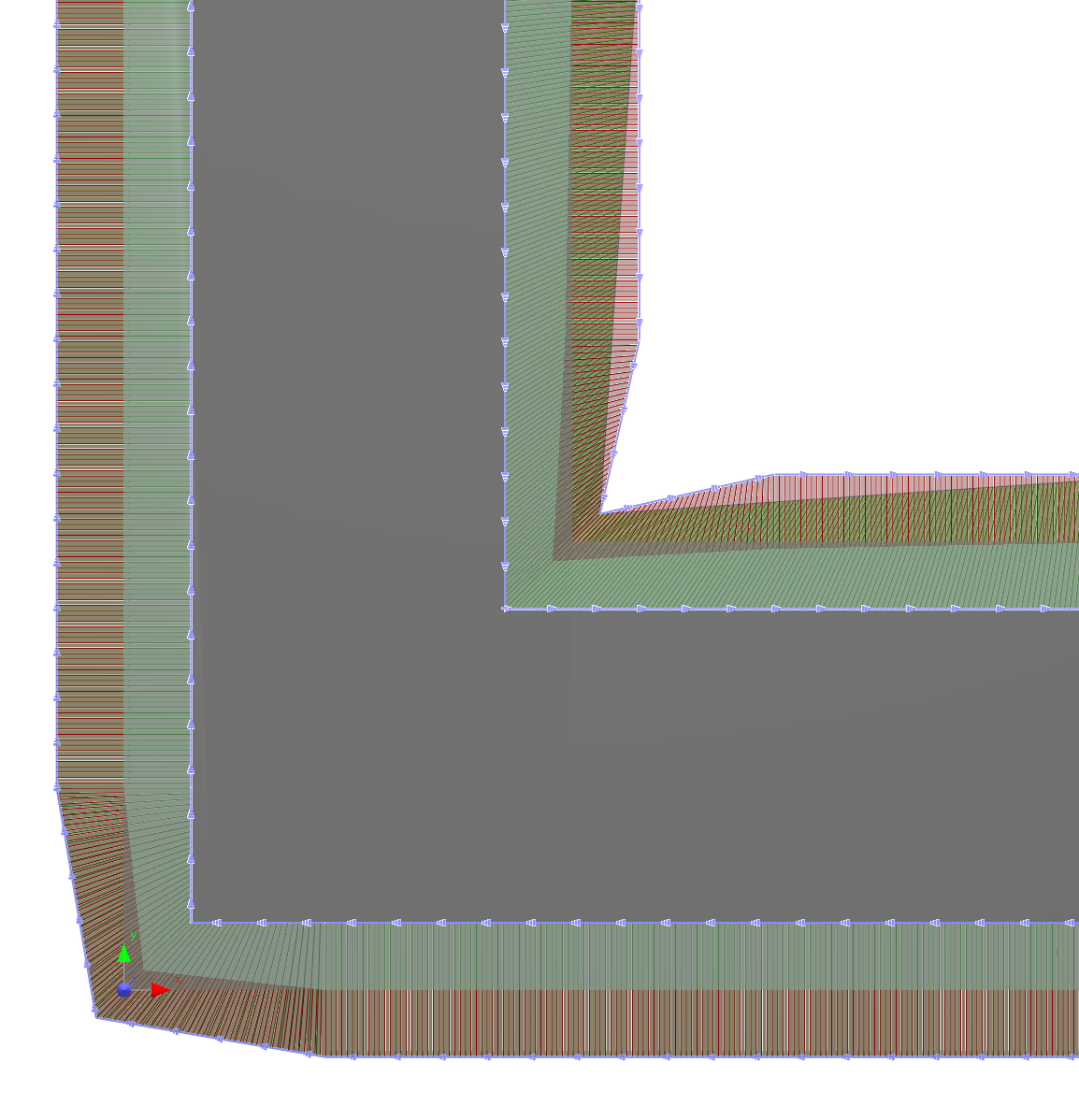
Below is the Preserve Top and Preserve Bottom bevels from the top view for clarification
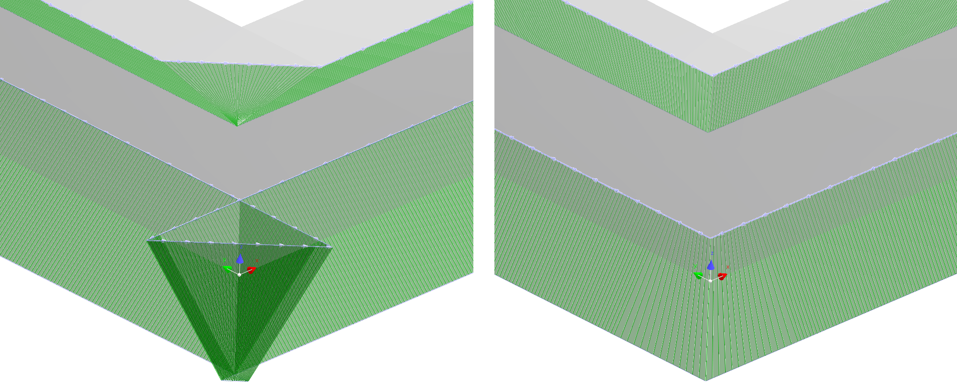
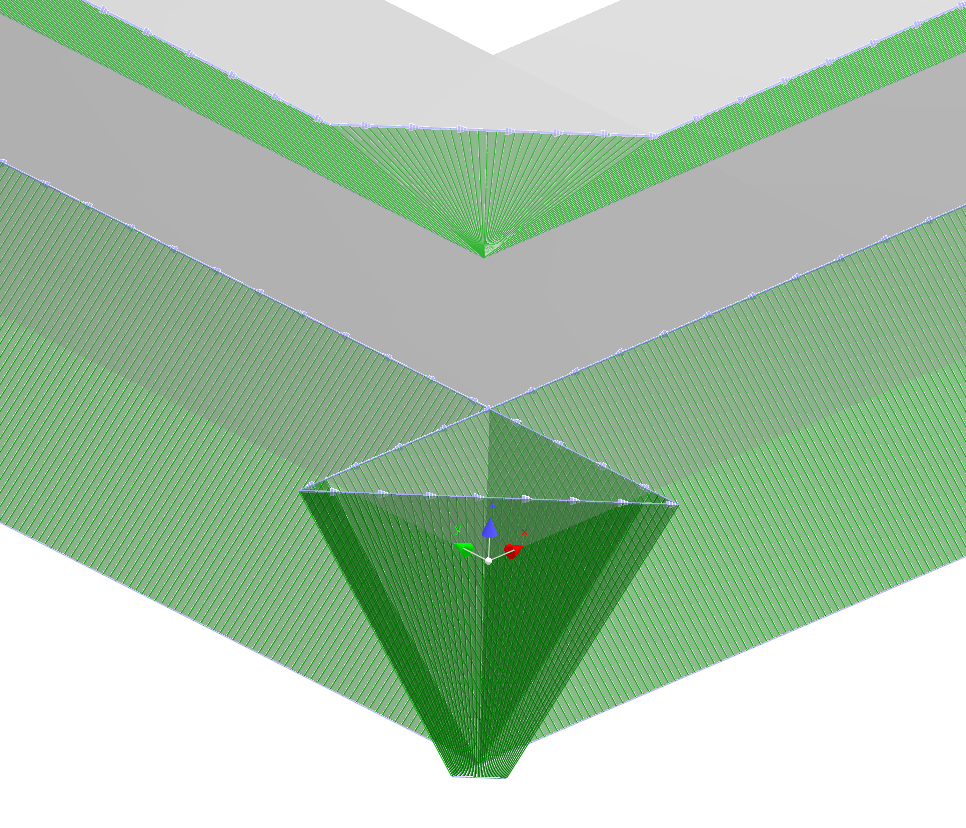
Double Bevel Mitering Beyond Max Bevel Angle
An un-mitered double bevel is shown below with 45 degree bevels top and bottom. The machine we are using in this example has a max bevel angle of 45 degrees, so will not be able to cut these corners without compensation.
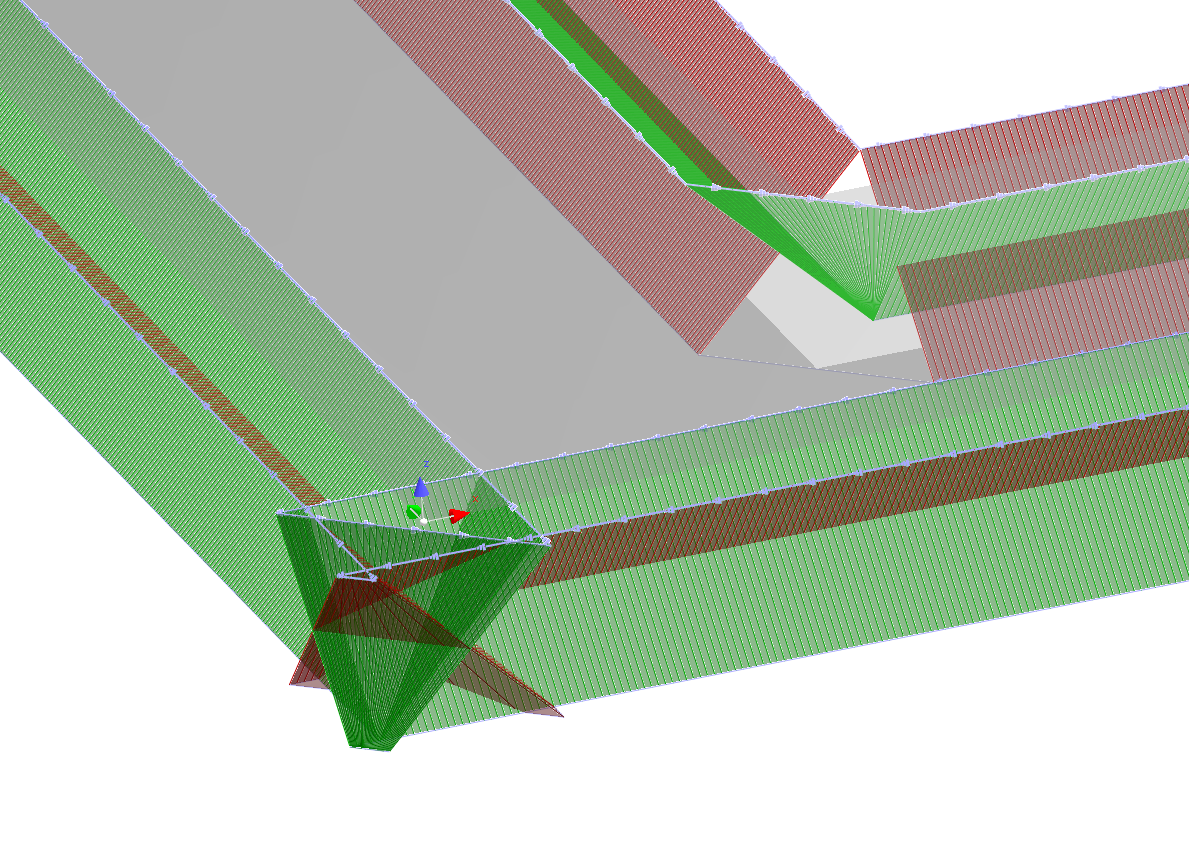
When mitering double bevels that have an apex greater than the Max Bevel Angle selecting preserve top for the top bevel and preserve bottom for the bottom bevels will mitigate a lot of the deformation caused by the compensation as shown below. Note that the top bevel with +ve angle is green and the bottom bevel with -ve angle is in red.
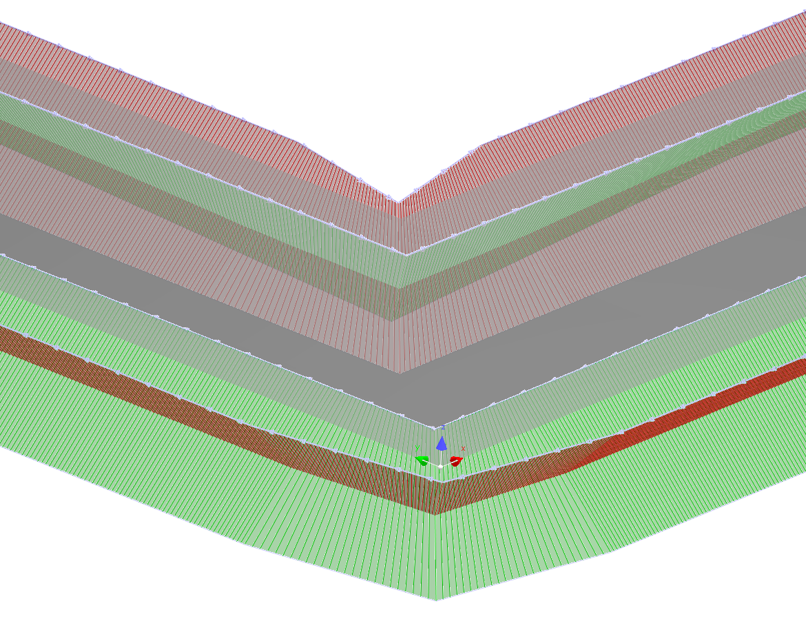
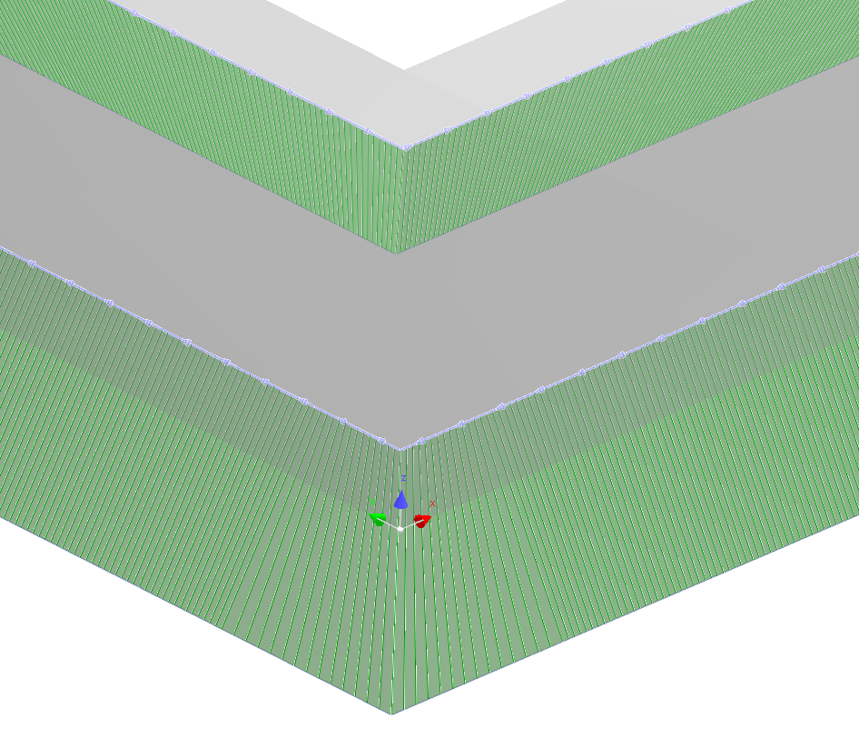
Below is the same corner shown from the top view for clarification
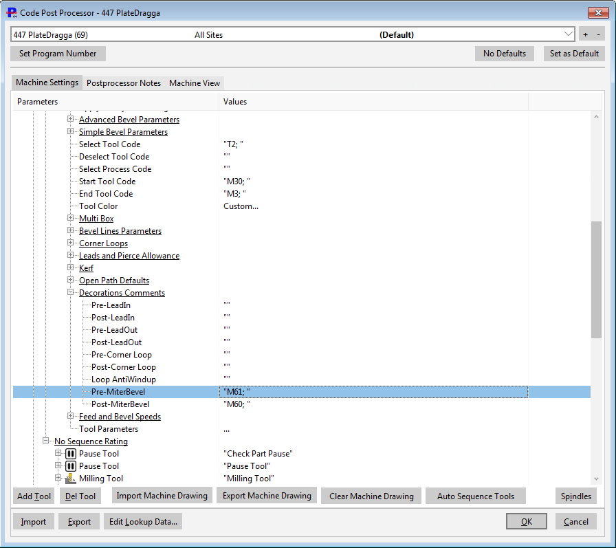
Disabling Torch Height for Miter Corners
When cutting a mitered bevel corner it is generally desirable to disable the automatic torch height control to prevent the torch from contacting the plate. The default will be to disable automatic torch height with the M61 (height control off) and M60 (height control on) commands as shown below.
Miter Flipping of Negative Bevels
A special case may occur where the adjacent segments differ in the sign of their bevel angles, eg a positive 30 degree transitioning to a negative 30 degree. To avoid unnecessary bevel head movements, PrimeCut can automatically convert a negative bevel to an equivalent positive bevel by rotating its azimuth angle by 180 degrees:

Before Corner Mitering and Miter Flipping. Note the top bevel is selected to show its initial configuration.

After Bevel Mitering and Miter flipping. Negative bevels have been converted into equivalent positive bevels.
If the adjacent segments are both negative, no flipping is performed. Be aware that if kerf or voltage correction tables are in use, the machine will be looking up the positive angle in its tables now, not the negative value.
If when prompted you choose not to flip the negative bevels, then a result like this may be produced:
 transitions.")
Corner Mitering with no Miter Flipping, and negative to positve bevel angle (and vice versa) transitions.