See Beveling Tutorials:
Multiple Bevel Wizard - 'Bottom Bevel + Land'
Multiple Bevel Wizard - 'K-Bevel'
In This Section:
Useful Information on Bevelling
Bevel Process and Bevel Segment Properties
For a full run through of the Beveling procedure in PrimeCut NE, see the beveling tutorials in the PrimeCut NE Tutorials, listed above
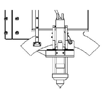
These instructions assume you are using a Kinetic Combination Bevel System.
Beveling is best applied in the part details rather than in the nest.
If you are importing a STEP or Native 3D CAD file beveling may automatically be applied when you process geometry.
If you are just working with a DXF or DWG type file then beveling won't automatically be applied.
If you are creating a single top or bottom bevel with no land, then select only the geometry that requires the processing in the processing editor, and click Process Geometry.
Select the Plasma Bevel tool for whatever type of path you have selected and select the angle. Note the given geometry will represent the maximum extent of the part - if a positive bevel is applied then the given geometry follows the bottom edge, if a negative bevel is applied the the given geometry is set to follow the top edge.
If the line you are given to follow isn't the maximum part extent line you should use the Create Bevel Geometry tool (See later on in this chapter), and enter the bevel details (setting land to zero).
Otherwise you can manually create the correct maximum extents geometry.
If the geometry is part of an existing closed loop, you may have to open the geometry in the geometry editor, right-click and click Explode to separate all the entities, and join the lines and arcs into path segments that are to be beveled and not to be beveled.
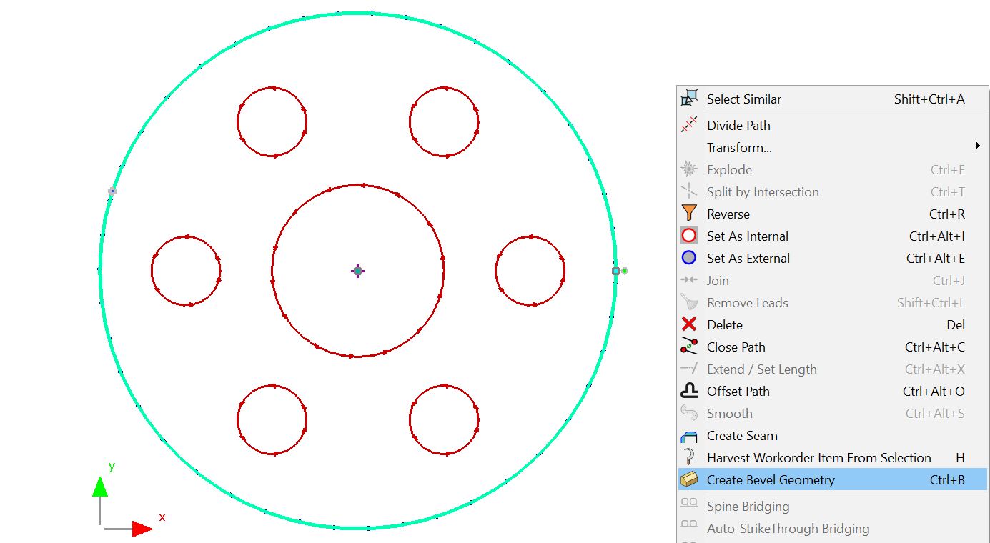
If you are creating a multiple bevels on the same geometry, it is easiest to use the create bevel geometry wizard.
Select the geometry, right click and click Create Bevel Geometry (CTRL-B) as shown below
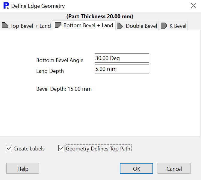
In the wizard, select the combination bevel you want. In order to ensure you don't create visually overlapping geometry we suggest you select Geometry Defines Top Path.
If you select the geometry that has the bevel, there should now be a Hints field in the properties window.
If you click the View button under that hints field you should be able to see what will override the settings in Process Geometry for these entities:

The same system of having a hints property on lines with bevel geometry allows PrimeCut to automatically process STEP and DSTV files with bevel geometry.
Note the following is important to keep in mind when you are beveling:
▪Be certain not to cut the part free before you finish cutting by leaving tags to be machined off the part later.
▪Preferably cut negative bevels, then land bevels, then positive bevels, so that the plasma torch isn't disrupted by an air gap until after it has finished cutting the edge of the part side, although experimenting and company preferences may prove another order more acceptable; for example if land is last, then corner loops may not be necessary.
Bevel Transitions: You can linearly vary the angle of a bevel over a single segment in the properties window by using the bevel angle and bevel angle change fields, and you can distribute a bevel transition over multiple segments using the Apply Bevel Transition Tool.
You can break a bevel segment into parts, using the Break Bevel Segment tool in the right click context menu.
You can also uncheck the Bevel Rotation Tangential checkbox to prevent the bevel tool from rotating with the geometry, and then manually control the rotation axis via Bevel Rotation Start and Bevel Rotation Finish.