A term used in sequencing to refer to a process still under its parent part in the sequence tree.
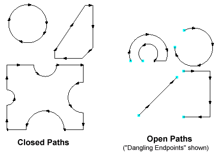
Closed paths are general "curves" composed of one or more segments, which wrap back on themselves, ie they have no Dangling Endpoints. Open paths have Dangling Endpoints.
Closed paths are normally desired for cutting purposes.
To cut material with the cutting tool not being perpendicular (at right-angles to) to the plate surface.
A tool used for beveling. Similar to a cutting tool but with additional properties. When a beveling tool is applied to a cut path a beveling process is created rather than a cutting process. Beveling processes often add corner loops, and add a bevel angle property to each segment of the cut path chain.
An arrangement of parts treated as a single "macro" part within PrimeCut. Used particularly when bridge cutting. See Clusters for more information.
Context menus are "context-sensitive" sub-menus whose contents depend on what the active selection contains. They are obtained by selecting something, then right-clicking. Think of them as a list of things you might want to "do" to the currently selected items(s).
This is a unique number used to identify and distinguish cutting and marking processes. For example the Costing ID of the Hypertherm HT4400 plasma running at 400A with O2/Air gases is 403, whilst Flame cutting with Harris Tips is 1000. It is only used on cutting, marking and beveling tools as the spindle costings are referenced by the tool specifier.
A Cutting tool is a tool applied to a geometric path. Cutting tools can only cut vertically, as opposed to beveling tools. Normally applied to Closed Paths. When a cutting tool is applied to a path, leadins and leadouts are normally added to avoid piercing on the edge of the part itself.
When geometry is loaded into PrimeCut, it attempts to join the geometric primitives (lines, arcs etc) together into chains, by matching endpoints of one primitive with the next. For cutting purposes these chains are normally closed, meaning the "head" of the chain meets the "tail" of the chain. Chains which are not closed are called open, and their endpoints are known as Dangling Endpoints.
A term used in sequencing, to denote a process which lies directly under the root plate of the sequence tree, as is generated by Global Optimization, rather than under a parent part (called an attached or part-attached process).
A drilling tool is any tool used to operate on a point only. It is usually but not necessarily a drill; it may be a marking tool configured to etch a point or cross, or a cutting tool configured to pierce only at the point.
Drilling tools are normally allocated to points and small internal circles (holes) less than a given diameter.
This refers to the scrap left from an internal cut, such as a hole. It's so-called because the "drop" is unsupported after the cut is complete, and if small enough as is often the case, may drop between the slats, or may partially drop to one side and be left sitting up at an angle, thus creating an obstacle the cutting tool may crash into.
Dross is the residue of solidified molten metal around the cut. Dross may form on both the top and bottom surfaces of the cut but is usually more prevalent at the bottom. Piercing may generate considerable top-side dross, especially on thicker plate. Tuning of cutting parameters and use of good tips/consumables can reduce or eliminate dross.
This is a part file format particularly common in the construction industry. Files often end in .nc1 or .nc extension (the latter is obviously also commonly used by G code programs). It can represent various structural members not just plate parts. At this time PrimeCut only deals with DSTV plate parts (DSTV Block designation "B").
A detailed description of this standard can be found here: DSTV Standard
See also DSTV (NC1) Part Import.
File format common among CAD systems. Contains geometric information about an object or objects. PrimeCut 3 supports DXF versions up to 14, but does not read embedded ACIS solids definitions.
Often called "Oxyfuel" or "Gas". A cutting process whereby the plate is heated under the torch tip to a very high temperature (beyond red-hot), and then a high pressure oxygen jet is fired which combusts (oxidizes) the metal. The combustion of the metal is exothermic meaning it generates more heat, and so the oxygen jet may be moved slowly laterally across the plate to cut it.
Generally used for cutting carbon steels, particularly heavy plate. Generates a lot of heat in the plate which may lead to heat induced plate movement.
A measure referring the minimum distance required between parts on a plate. Too narrow a gap and the cut around one part may affect the cut around its neighbor adversely. Having too big a gap results in wasted material. The size of gap chosen depends on the thickness of the plate being cut and the cutting process. Normally heavier plate will require a larger gap.
The minimum gap between parts on a plate is a property of plates, called Gap Size. PrimeCut now allows the gap between parts and the edge of the plate to be set separately through the Edge Gap Size plate property.
Also known as Full Kerf, Kerf Diameter.
The width of a cut made by a cutting tool. This varies depending on the tool but it must be taken into account in order for parts to be cut the right size. Sometimes the term may be used refer to its half-value, refer Kerf Offset.
The half-kerf (Kerf Offset/Kerf Radius) is the distance used to offset the tool path so that the final cut part is the correct size. Often this kerf offset is done by the machine itself which allows small adjustments to be made at the machine, but sometimes the programming software may do it.
See also Kerf.
Kerf Side: Kerf Left/Kerf Right/Kerf None
When cutting parts the cutting tool is offset to one side of the geometric path slightly to accommodate kerf. Normally Kerf Left is used, meaning that, looking along the direction of cut, the tool is offset to the left of the part. This means that the outside of parts is cut in a clockwise direction, while the inside is cut counterclockwise. This would be reversed if Kerf Right was used.
When using plasma, Kerf Left should always be used, due to the swirl direction of the plasma gas. It is less important which kerf direction is used when flame cutting, though convention has it that kerf left is still the norm. If this were not the case, then the path directions for gas cutting would need to be reversed. In short - you should only use Kerf Left.
These are the most commonly used properties within Properties Dialogs. They are usually a different color (blue or maroon for example) to make them visually distinct.
Many cutting process have a property called Lag. This indicates that the cut at the top surface of the plate is slightly ahead of the cut at the bottom surface. Reading Lag Lines on the edge of plasma or flame cut parts is a way of assessing whether the cut speed is to fast or too slow.
This is a laser spot light installed on some machines (all Kinetic machines) to make plate location and alignment more straightforward. It is called a tool on the machine, but is not a "tool" in the PrimeCut sense as it does modify the plate in any way.
The extra cut a tool makes prior performing the actual cut required. This extra cut is required because the tool may make an irregular opening, and may generate top side dross, when it first pierces the plate.
The extra cut a tool makes after performing the actual cut required but before leaving the plate. Sometimes necessary to completely finish a cut on thick plate (due to lag), and sometimes aids in prolonging consumable life (especially when plasma cutting).
This is a unique number (unique within a database) assigned to a controller/machine. It is this number that the Machine Integration references when connecting a TouchCut Machine to PrimeCut. See Connecting TouchCut To PrimeCut.
It is also used to link machines to parts and plates- it cannot be changed if any parts or plates in the database already refer to it.
A marking tool is used to mark the plate, not to cut it. As such it is a surface operation and independent of material thickness. Marking may be used to mark fold lines, weld datums, and for part labeling. Examples of marking tools include the Hypertherm Arcwriter, Hypertherm HD4070 systems running marking processes, Innerlogic Fineline systems running marking processes, pneumatic scribers, inkjet heads and powder markers.
Multibox, also known as "Multi-torch" or Multi-carriage", is the term used to refer to the uses of more than one cutting (or drilling or marking) head at a time on a machine. This is when up to ten heads are cutting at once, and each head is mounted on its own carriage or "box".
As some machines support one tool (such as plasma or flame) across several boxes and others only one (such as the spindle), combining these processes with multibox nested parts can yield programs where boxes must be spaced and unspaced throughout the program.
PrimeCut provides full support for this.
Numerical Control codes. These codes actually control the cutting machine directing it to move in a straight line, along an arc and to activate or deactivate a particular tool. PrimeCut supports both EIA ("G-Code") and ESSI type instruction formats. These are imperfect standards, in that almost every machine manufacturer takes the basic instruction set and augments or modifies it to suit the particular functionality of their machines. It is the function of the postprocessor in PrimeCut to perform any translations and customizations needed for a given machine.
A Nest is an arrangement of parts, represented by part inserts, on a plate.
A part-by-part sequence order in which parts are ordered in the same order as they were nested. The sequence within parts is the part sequence, if it has been set.
In the context of PrimeCut, a part is something we can cut from plate.
A basic 2D shape that is to be cut from plate or sheet. A part is normally a single piece of metal but it may have holes in it. A part can be used as a flat two-dimensional object like a spanner or it can be bent or folded into a three-dimensional shape like a cube. A part can have "2.5D" geometry such as milling and drilling to depth, and may have beveled edges.
A part may be composed of a cluster of sub parts; this is called a cluster part.
This is how we record the location of part within a Nest. A Part insert stores the position and rotation of a part on a plate, but can also refer not just to a single part but to an array of similar parts.
See also What is a Part Insert? .
A path is a chain of geometric primitives joined together by their endpoints. A path may be open (the simplest open path consists of a single line) or closed (the simplest closed path consists of just a circle). A path cannot contain points or text. An open path has Dangling Endpoints, a closed path does not.
Plasma tools are cutting and/or beveling tools used for a cutting carbon steels, stainless steels and aluminum. They operate by passing a large current from an electrode in the torch through an arc (superheated ionized gas) to the plate. The superheated plasma of the arc vaporizes and blasts away the metal beneath it.
The metal sheet from which the shape will be cut. Sheets are often rectangular but may be irregular in shape particularly if remnant plates are used. Can also refer generically to the nest and processing information which is applied to a virtual plate within PrimeCut.
Processing is the application of tooling information to geometric part data. This includes tool allocation, kerf offset, leadin/leadout placement and cut ordering.
A PrimeCut proprietary file format for storing part data which carries not only geometric information but records additional information such as processing and job tracking data (customer, job, material). Parts can be exported to NEPrt files and transferred between PrimeCut NE databases, allowing tool remapping to occur as the parts are imported.
Any plate that is leftover from a previous usage and still large enough to use again. A remnant plate may be irregularly shaped. Also known as an Offcut.
The material that is leftover after a set of parts is cut from the plate. Especially material that is not used again, i.e. is not remnant plate. See also Drop.
The order processing is performed in. Changes to the sequence are performed in the Sequencing Editors.
A table indexed by hole diameter storing drill, tap and counterbore sizes to be used.
Each diameter may map to a single spindle operation, or to a sequence of spindle operations.
A spindle tool is a large drill which supports selection of the drill bit via the NC program. A spindle may also support other operations, such as tapping. A spindle is often equipped with an automatic toolchanger. PrimeCut uses a Spindle Allocation Table to automatically choose and program which spindle tooling to use on a given size of hole.
The actual drill bits and taps useable within a spindle tool, i.e. not the spindle tool itself.
STEP is a modern standard for the exchange of various types of information in manufacturing. PrimeCut can import STEP AP203 and STEP AP 214 files; these represent 3D CAD models, and many CAD systems support export and import of these.
See also Part Processing and Importing a Solid STEP File, Pad Milling from 3D STEP Import, 3D CAD Native Part Import Plugins.
A workspace stores the current state of a PrimeCut job, namely the parts, plates and any processing and nesting that has been performed. Workspaces can be used to store parts lists for "kitsets," a set of parts used to construct a particular object.