When milling downward into material there are a number of different options and switches to control how the tool will move. Understanding these, and your tooling, will help you minimise milling time and maximise tool life.
When PrimeCut is milling to a depth, it will often need to do this in a number of depth passes. taking too deep of a cut at once will overload the spindle and likely break the tool. There are occasions when a single pass is sufficient of course, milling the side of a part when the material is not too thick for instance.
There are two main techniques (Movement Types) available to get the tool to step downward in multiple passes: Layers and Helical (ramped). You choose which you will use when applying the processing; you cannot change a ramped milling process to a layered one via properties or vice versa, you must reprocess it to change the movement type.
A Local Coordinate System (LCS) can be used to move milling in 3 Dimensions, but especially in the Z Direction. The Z Ref. Plane setting is a means of setting the LCS Z ordinate.
The layers technique can be applied to any milling geometry, to open or closed paths. Essentially the tool mills around the part at a fixed depth (constant Z), then plunges a Depth Increment to the next layer and repeats. At the end of each layer the tool will be sent a stop code and will move back to the start and start again. There are however some tricks we can use to optimise this, see in particular the next section on Ramped Leadins.
TIP Choose the depth increment as large as possible, within the force and torque limits of the tooling and spindle:
* Minimize milling time
* Use a greater depth of the cutting teeth on the tool, thus increasing its effective life.
If for example your depth increment is set very small, say 1mm, then only the bottom 1mm of the mill will do all the cutting work.
The Depth Increment is key in specifying how far between each layer vertically. You will notice that there is also a readonly value Z Increment (Effective), PrimeCut takes the requested Depth Increment and tries to divide it evenly over the total Z Travel be milled (Z Begin- Z End in Z Mode, or Feed From Height+ Depth in Depth Mode). Usually It won't divide evenly unless you are lucky, so if there are (say) 2.5 of the requested Depth Increments in the Total Z Travel, then this gets rounded up to 3, and the effective depth Increment in use will be (Total Z Travel/3).
In the Details below you can see a summary of the process defined. Note that the First Pass of the tool is at Z = -5mm, more generally it will always be Z Begin- Depth Increment (Effective).
A Finishing Depth Pass (Using a Finishing Depth Pass ) can be used to control the final depth pass thickness and activate Finishing Settings.
Many milling tools have a specified angle of attack with which they should be brought down into a workpiece, most for example should not be plunged vertically. Ramped Leadins provides a method where the tool can move down into the workpiece along a slope, along the leadin in fact. A ramped leadin is different to most leadins, in that the tool will start at the END of the leadin, traverse backwards along it while ramping downward into the material, until it reaches the start of the leadin at the depth (z) required for the current layer. It then reverses and travels forwards along the leadin at a constant depth (Z) and continues on around the path it is to mill. We recommend NOT using leadouts when using ramped leadins; that way on a closed path, when the path completes, the tool is already at the correct XY and Z to start the next layer.
Try to ensure that the combination of your leadin length and depth increment produces a suitable Ramp Angle. In the example below you can see the Ramp Angle achieved is 14 degrees, this is shown in the Details memo. Also note the comment "Continuous Ramping, no retracts"- this is a good thing, achieved through having a ramped leadin and no leadout, on a closed path.
When would you not use Ramped Leadins? If you have a drill capable of plunging (sometimes called a slotmill or slotdrill), or when you can plunge away from the workpiece and leadin horizontally to the material.
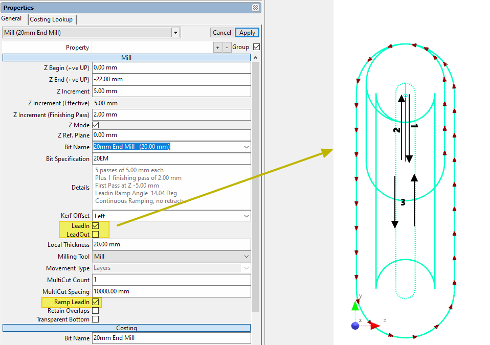
1) Beginning at the leadin attachment point, the tool travels backwards along the lead while ramping down into the material, 2) On reaching the start of the leadin the tool has descended to the correct height, and returns along the leadin at fixed Z, 3) the tool continues around the path (its centerline will follow the dotted path) at fixed height. When it completes, it is in the correct loaction to start another rampdown (1) to the next layer (only if the path is closed and there is no leadout)

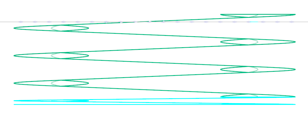
Side View of the above Ramped Leadins
This can only be applied to closed paths. The tools "spirals" slowly down into the workpiece with a "pitch" equal to the Depth Increment. This is a smoother technique than layers, with no lifting the tool off the workpiece. Despite the name, it can be applied to any closed path, not just circles. Leadins and leadouts are forbidden, and not needed using ramping. When using helical ramping, when the tool finally reaches its target depth (or Z Finish), the tool must complete another full circuit of the path at constant height to ensure it has milled a flat bottom. Thus a disadvantage of Helical milling is that for a given depth increment, there is 1 extra loop around the path. This however effectively provides a "built in" finishing pass, and the benefits of its simplicity, and lack of leads or plunging, generally make this advisable for milling out internal holes, slots and simple pockets.
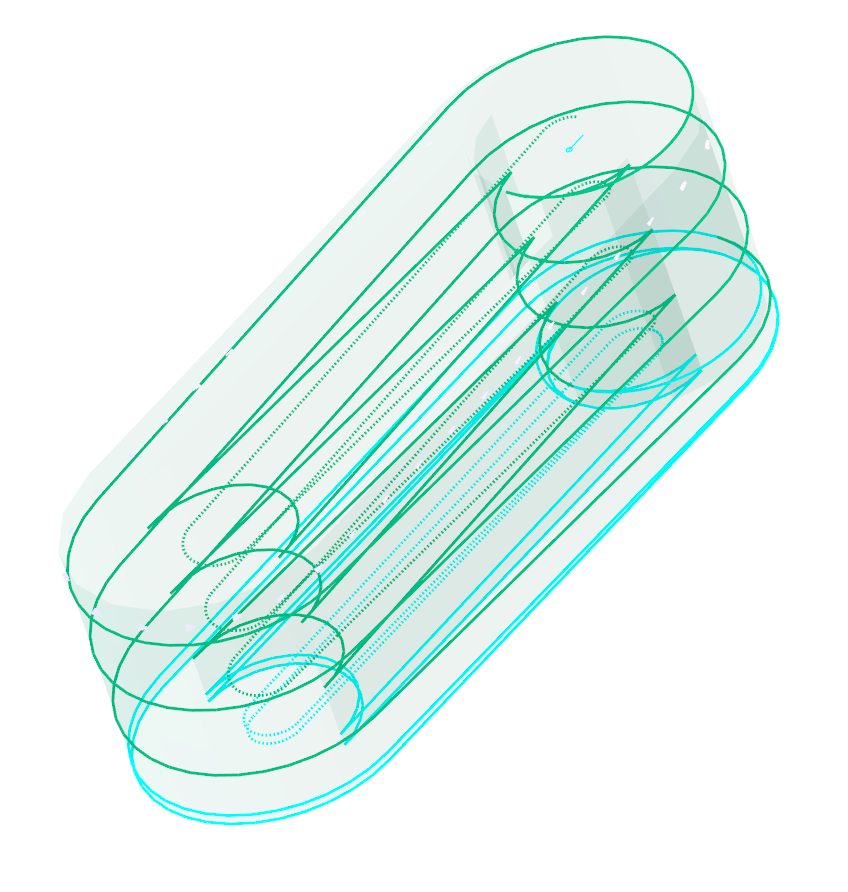
Side and isometric views of the same slot, milled with helical Interpolation. No leads, and we have started 2mm above the nominal top surface of the workpiece.