See also Auto Breakup of Skeletons for an alternative means of skeleton breakup.
Skeleton Breakup is particularly important on "passthrough" machines like the K5600 Platedragga. The idea is to cut a columnar region of parts on the plate and sever the plate completely, ideally such that the last cut runs from the bottom edge of the plate, up the left edge of the parts, to the top edge of the plate. Using Crop variants Smartcluster functionality ( SmartCluster: Common Line and Common Crop Cutting, SmartCluster: Chain Cut and Chain Crop) give us efficient and powerful control of how the plate is broken up, while Auto Breakup of Skeletons which can be performed by the sequence optimizer is more automated but generally less reliable in terms of plate movement.
In a perfect world, the plate will be perfectly rectangular, and the exact size that PrimeCut thinks it is. In the real world however, the plate edges may bow slightly, be rolled rather than a distinct hard edge, and the plate is almost never exactly the size we think it is. We can apply some edge-start and edge stop settings to the cutting tool in the machines section that help the machine to deal with this.
If we assume the plate is loaded and held against datums while cutting, then the bottom edge where the severance cut begins is fairly well known. We can however automatically add a small leadin, or shrink the start of the cut slightly to optimize the pierce point relative to the datums.
More importantly, as the plate width is not precisely known, and will usually be slightly bigger than we expect, we can add a special leadout to carry the cut beyond the theoretical plate width as far over as we think we will ever need to go to fully sever the skeleton. Additionally we can insert a code into the G-Code program to tell the machine to ignore loss of arc during this segment, otherwise it is likely the machine may consider that the loss of arc before the end of the cut to be an error condition and stop. On TouchCut controllers we insert M4 just before the leadout.
The cutting tool edge start and stop settings are set as follows in this example:
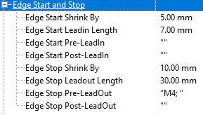
In this case we are shrinking the start of the cut by 5mm and adding a 7mm leadin, thus the cut will start 2mm behind the nominal plate datum. There is little practical difference between this and just adding a 2mm leadin, however a longer leadin improves visualization during nesting.
The cut end shrinks by 10mm and adds a 30mm leadout, effective dealing with errors in actual plate size of -10mm to +20mm, and the Edge Stop Pre-LeadOut code of M4 is set to ignore arc loss warnings in this segment.
A Common Crop Example
The image below shows a section of passthrough nest, cutting 12 squares, each with some drilling and marking as well.
To achieve this nest we first array a single column of 3 parts, then SmartCluster, Common Crop it. This produces a commonline nest, where we will cut the 2 horizontal cuts between squares first, then a large "]" shaped cut across the top and down the right edges and across the bottom of the parts. Finally we perform a straight severance cut from the bottom of the plate to the top. All this is setup automatically by the Common Crop. We can then array leftwards this column to create 4 columns as shown:
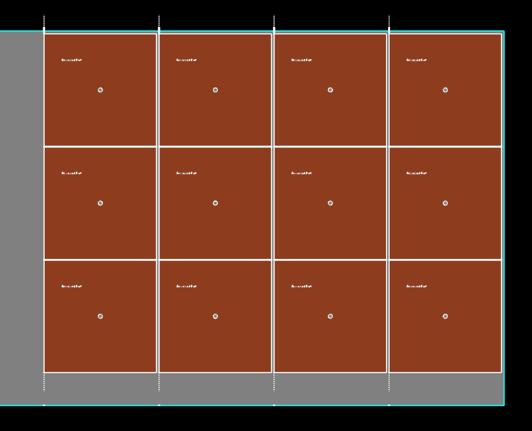
In nesting mode the breakup cuts are indicated by the dotted extensions- these are displayed a fixed length and do not need to cross the plate edges. Because of our edge start and stop settings creating edge leads we can see these edge crossing points rendered as well.
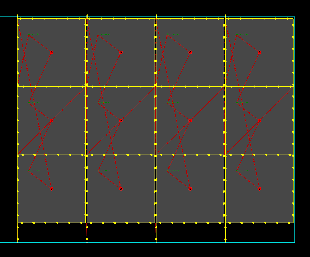
In the processing editor we get a better view of the severance cuts and their actual paths:
See Also