The I Beam Section is the cross-section outline of a rolled steel I beam or H section: two equal flanges, top and bottom, joined by a central web. It is sized the way steel section tables give it - Depth, Width, Web Thickness, Flange Thickness, Root Radius and Toe Radius - with an optional Flange Slope for taper flange beams. Use it to cut a profile that matches a beam, for example an end plate, a cope template or a hole in a plate for a beam to pass through. It is also found by the names I Beam, H Beam, H Section, Universal Beam, Universal Column and RSJ.
It appears in the shapes library under Other Shapes.
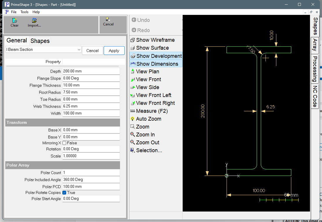
I Beam Section in PrimeShape: the property page (left) and the shape with its dimensions (right).
Insert point and orientation
The insert point is the bottom left corner of the section extents - the outside bottom left corner of the bottom flange. Width is built to the right along X and Depth upwards along Y. The web is vertical and centred at X = Width / 2; the flanges lie along the bottom and top edges. The section is symmetrical about its vertical and horizontal centre lines.
The shape is one closed outline, built anticlockwise from the insert point. Root Radius rounds the four inside corners where the web meets the flanges; Toe Radius rounds the four inside corners at the flange tips. The four outside corners of the flanges are always sharp.
Properties
Lengths are in the current units (mm or inches); Flange Slope is an angle. The defaults shown are for a new shape; the inch defaults are used when the program is set to inches. The table follows the order of the property page.
Property |
Description |
Default |
Depth |
Overall depth of the section, outside of the bottom flange to outside of the top flange, along Y. Must be greater than zero. |
200 mm (8 in) |
Width |
Overall width of the flanges, along X. Must be greater than zero and greater than Web Thickness. |
100 mm (4 in) |
Web Thickness |
Thickness of the web, measured across it along X. The web is centred on the Width. Must be greater than zero and less than Width. |
6.25 mm (0.25 in) |
Flange Thickness |
Thickness of each flange, along Y. With a Flange Slope it is measured half way along the flange outstand (half way from the web face to the flange tip), as section tables give it. Must be greater than zero. |
10 mm (0.4 in) |
Root Radius |
Radius of the fillet at the four inside corners where the web meets the flanges. 0 leaves those corners sharp. Cannot be negative. |
7.5 mm (0.3 in) |
Toe Radius |
Radius at the inside edge of each of the four flange tips, where the inside face of the flange meets the tip. 0 leaves those corners sharp. Cannot be negative. |
0 |
Flange Slope |
Slope of the inside face of the flanges, in degrees, for taper flange beams. 0 gives parallel flanges. From 0 to 45 degrees. See below. |
0° |
The dimensions drawn on the shape are Depth, Width, Web Thickness (across the web at mid depth), Flange Thickness (on the top flange, half way along the right outstand), Root Radius and Toe Radius. Each dimension is named after its property, so clicking it edits that value. The Root Radius and Toe Radius dimensions are drawn on the top right fillets and are hidden when the radius is 0 or when the radii are too large to fit.
Flange Slope
With a Flange Slope the inside face of each flange slopes, so the flange is thinner at the tip and thicker at the web. The outstand is (Width - Web Thickness) / 2. The flange thickness changes by tan(Flange Slope) x outstand / 2 each side of Flange Thickness:
•thickness at the flange tip = Flange Thickness - tan(Flange Slope) x outstand / 2
•thickness at the web = Flange Thickness + tan(Flange Slope) x outstand / 2
The outside faces of the flanges stay flat.
Limits
If any of the following is true the shape is not built and the property page shows Warning: Cannot build shape from these parameters:
•Depth or Width is zero or less.
•Web Thickness or Flange Thickness is zero or less.
•Web Thickness is equal to or greater than Width.
•Flange Slope is less than 0 or more than 45 degrees.
•Flange Slope is so steep that the flange tips have no thickness (thickness at the flange tip, above, is zero or less).
•The flanges are too thick for the Depth: twice the thickness at the web is equal to or greater than Depth, so there is no web left between them.
•Root Radius or Toe Radius is negative.
•Root Radius or Toe Radius is too large for the section. Each fillet uses a tangent length of radius x tan(half the turn angle) on each side it meets. On any one side, the tangent lengths at its two ends must not add up to more than the length of that side. With Flange Slope at 0 every corner is square, so the tangent length is the radius itself and the limits are: Toe Radius no more than Flange Thickness; Root Radius plus Toe Radius no more than the flange outstand, (Width - Web Thickness) / 2; two Root Radii no more than the straight web between the flanges, Depth - 2 x Flange Thickness. With a Flange Slope the tangent lengths are shorter and the sides longer, so the exact check in the code governs and these limits are approximate.
Every 2D shape also has the Transform properties (Base X, Base Y, Rotation, Scale, Mirroring X) and the Polar Array properties, listed after the shape's own properties.