DEPRECATED SmartCluster: Common Line and Common Crop Cutting now provides more automated tools to support this functionality, however in some special cases you may need or want to still use the older functionality
See example here.
Common line cutting describes the situation where you use a single tool pass to cut the edge of two parts simultaneously. This feature should be used judiciously with plasma tools because they produce a better cut on one side due to the swirling of the gasses, unless the edge quality is not important. However is milling or oxy is being used common line cutting becomes a valid option.
1.In the Nesting Editor, nest the parts on the plate using an array.
2.RIGHT CLICK on the array and select Create & Edit Cluster from the context menu. The part will now be opened in the Part Geometry editor.
3.Press the Common Line Cutting button. A dialog will appear asking you for the Kerf Offset value. This value is from the centre of the tool to the edge of the cut (radius not diameter). This value should be taken from the machine controller running TouchCut. It is critical that you enter the correct value, otherwise the parts will be incorrectly sized.
The mouse pointer will change to a square and you will be able to select geometry on screen.
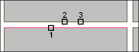
4.Click on the part edges you would like to common line cut, and then click on the last edge again to join them as shown below.

Do the same for all of the joins you want to create. If you make a mistake you can press the Common Line Cutting button again and select Undo Last Join to take back the last change, or Cancel to return to the geometry you started with.
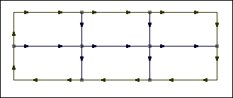
5.When you have made all of the required joins, press the Common Line Cutting button and select Done from the menu. The resulting geometry will then be displayed.

In some cases you will encounter the situation shown above where one or more of the internal lines consist of more than one path. You will need to join these otherwise there will be a new pierce at the beginning of each path. Select each of the paths in turn to see if they are separate or joined.
1.To join the paths press the Corner Join button in the Geometry Editor, then click on the paths you want to join. You will need to do this in the direction of the arrows for it to work.
2.When you are satisfied return to the plate and apply processing. When you do this go to the Advanced Options for the cutting tool you are using and ensure that No Leads for Open Paths is unchecked (we do want to use a leadin and probably also a leadout), and No Kerf for Open Paths is ticked (we don't want to use kerf because the path that has been created is exactly where we want the center of the tool to be. PrimeCut actually applies No Kerf Hints to the geometry when it creates the common lines (as they have been pre offset), so no kerf should be applied regardless of this setting ).