See also Import Machine Files : This is a critical step for synchronising Primecut's tool and gripper positions and collision zones with those of the Machine.
Passthrough “PlateDragga” style machines add some extra requirements to the programming task. The following tips will help when using PrimecutNE to nest for a passthrough style machine, such as the K5600:
•Nesting: Nest Right to Left (nest from right hand edge of plate back towards the back grippers)
•Nesting: use the “Edge preference: Prefer Top” to nest parts along the top of the plate, this will leave more space for the side grippers to work with along the bottom edge of the plate.
•Processing: Leadins should be placed top left when possible. This will usually mean the plate is stationary on the bed during its final severance cut up the left edge of the part.

There are some tools to assist with this leadin placement. You can manually reposition all leads on a plate in the processing editor by selecting all (Ctrl-A) and then pressing Ctrl-6, which is “place leads top left”. You van also automate the process so that leads are placed at top left automatically after nesting by adjusting some tool settings in the machine section- see below
•Sequencing, main tab: Settings such as those shown below are recommended, in particular ensure sequencing starts at the Top Right corner of the plate with narrow zones and a stronger than usual horizontal tendency. Part by Part is recommended also to reduce the chance of holes moving relative to the enclosing part. Auto Shutter Drop Small Parts (very small parts will be dropped inside the opening cut shutter) should be selected on machines where the parts are pushed across gaps onto the part elevator, Auto Trapdoor Parts should be selected and will drop all parts that fit within the part elevator extents, and Auto Skeleton Breakup will progressively cut up the skeleton and drop it via the part elevator.

•Sequencing, Trapdoor Settings: Should be set to Trapdoor Every Drop (recommended), or Trapdoor Every Part. The difference is that the former will also drop large internal cutout pieces of scrap from within parts, as well as after the external part cut. This is generally more reliable. Min Droppable Width sets a lower part “width” limit on what parts are to be trapdoored.

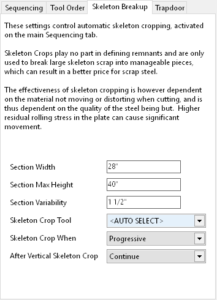
•Sequencing, Skeleton Breakup: Set a Section Width smaller than the trapdoor aperture, ie smaller than the part elevator width. Section Max Height may also be set to create horizontal skeleton crops to break the skeleton sections into manageable pieces. Section Variability should be set to allow the vertical crops to “shuffle” a little if needed to reduce the amount of cross plate cutting. Section Crop Tool can normally be set to <AUTO SELECT> which will choose the first cutting process in the nest. Sometimes no cutting process can be found in which case the skeleton crops will be left unprocessed and must be manually processed with a cutting tool; alternatively you can select the cutting process you want to use explicitly in the Skeleton Crop Tool setting. Skeleton Crop When must be set to Progressive. See also Auto Breakup of Skeletons.
Tool Settings To Automate Leadin Placement At Top Left For Cutting Tools
In the Machines section ensure the following settings are configure for ALL cutting tools. These settings cannot be applied to beveling tools, as bevel tools have more specific leadin placement requirements.
Under the cutting tool’s Lead Placement Section the following settings should be configured:
•Lead Flexibility : Flexible. Allows leads to be moved and resized automatically after manual and automatic nesting. Also allows more efficient nesting of parts as leads “fit in with the nest”, rather than the other way around.
•Nest Friendly Lead Placement : True. Not essential but places 30 degree arc leads on parts making them fit nests more easily especially when nesting quantities of rectangular parts. Allows the Flexible leads to also use this leadin style when needed.
•Location Tendency H: Tend Left, Location Tendency V: Tend Up. Horizontal and Vertical lead placement tendencies. These push the leads to the top left of the parts, and in conjunction with Lead Flexibility above, pushes them to the top left of the parts as nested.

Bevel Genius Recommended Settings
As well as cutting tools leading in at top left as set above, we would also like our bevel tools to leadin at top left where possible. Many bevel processes are applied to open paths, especially when creating composite bevels, and the leadin placement for these paths cannot of course be altered- you must leadin at the start of the open path and leadout at the end… end of story. However frequently there is a final closed path which contains lands and/or top bevels, being the “topmost” cuts in the part. This is the cut that finally severs the part from the plate.
There are 3 requirements we seek to fulfill on positioning these leads, one of which is specifically beneficial to pass-through/ “PlateDragga” style machines:
1.Leadins at top left – so the final severance cut is across parent plate material and while the part is as firmly attached as possible to the plate. On the PlateDragga, this also means the part is severed “downstream” of the cutting aperture and with the plate generally not moving.
2.The cut start should avoid being placed immediately after a compound bevel; if we do place them here then the part will be fully severed from the plate before the final cut completes (see example). We thus avoid placing leads in these positions. In combination with the “top left preference” above, this suggests certain nesting orientations of the part will not work, in particular the orientation with the compound bevel along the left edge of the part as nested is undesirable.
3.PlateDragga specific: It is optimal to have the plate stationary when doing our bevels, where possible, that is for the bevels to be aligned with the machine short (Y) axis. Given 2) above, the best position for the bevels will be the right hand edge of the part. For parts with bevels on multiple or opposite edges, this is not attainable, however many parts do fit this criterion.
The recommended Bevel Genius settings are as follows:

See Also