In this tutorial we will look at how to perform a cut using two plasma bevels, with one cutting a +30º bevel and the other a -30º. We will be nesting two tower "trap" profiles back to back, and then setting up the cutting paths and processing with MultiAxis. See MultiAxis (Independent Short Axes).
Steps 2 through 5 below demonstrate use of the Align Edge function for manually laying out the towers sections; this allows great flexibility in positioning them, however Autonesting can also do this quickly.
1Open the parts and plate in nesting.
2Drag one of the parts into the nesting area (or Autonest and skip ahead to Step 6).
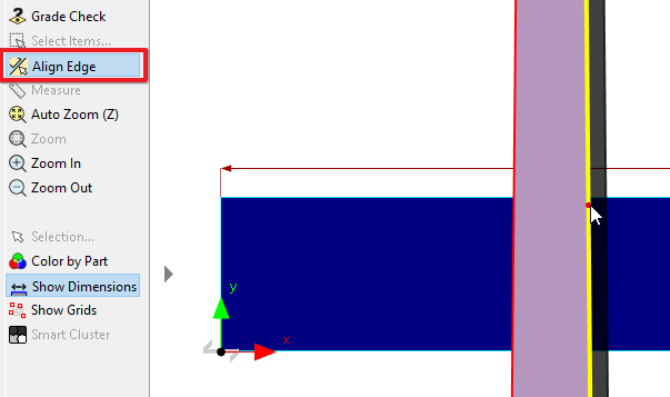
3To make on of the long edges parallel with plate, we will use Align Edge. Click Align Edge and then select the right side of the part. Four red lines in a box shape will appear. Hovering over a line allows you to preview that alignment option - we want to select the top line.

4Use bump nesting to position the part at the bottom left corner of the plate.
5Drag the next part onto the plate, then click align edge and select the left hand edge of the part. Hover over the top edge of the first part so the edges snap together then move your mouse to slide the part to the far right of the plate as shown below. Click to place the part. This minimizes the height of the nest, in this case more to exemplify what needs to happen when the tower traps are staggered.

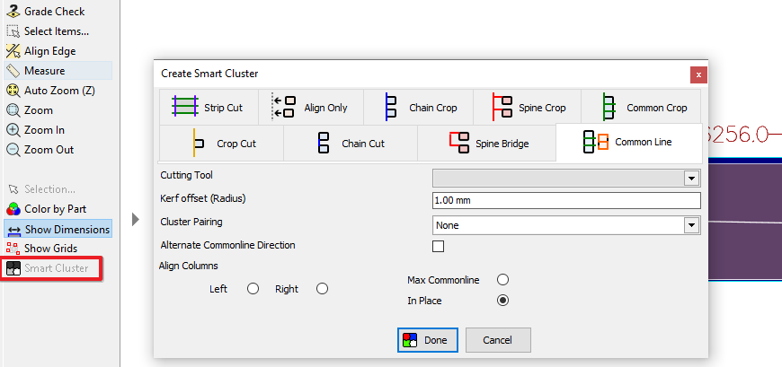
6Select the two nested parts and click smart cluster. Choose Common Line, with a Kerf offset of 1mm and click the In Place radio button- this keeps the tower sections in the same horizontal position as you have manually indicated.

7Select the cluster, right-click and add the cluster to the parts list so we can edit it. Right click the cluster in the parts area and click edit. Close the warning about changes affecting the nest.
In the geometry editor we can see that the perimeter of the cluster is a single path. When cutting a continuous path around a long thin part like this, the stresses in the part will often deform it. To get the best results, we should cut the top and bottom path simultaneously.
8Select the top segment and click segment cut from the context menu. Use CTRL + V to paste the segment back in the same place but as a separate path.

9Repeat the above step to separate the bottom segment.
10When using MultiAxis the paths must be processed with no kerf offset, so we need to create the offset manually. Select the top and bottom paths and click offset path from the context menu. Set a 1mm offset (or whatever kerf offset was used at Step 6 )and click OK, then click No as we don't want the original segments.
The two simultaneous cuts need to start and end at the same x coordinates, and move in the same direction.
11Select the bottom path, right-click and select reverse in the context menu. )
12With the bottom path still selected, note the X-coordinate of its the start point (in the properties window). Hold control and click the top path, so both are selected. The start and finish properties will now be highlighted yellow, indicating that it is not the same for both paths.
13Click the highlighted box next to Start Point : X. It will auto-fill with the start point of the bottom path. Click apply to make the starting point of both paths the same.
It is very important to select the paths in the correct order when using this feature - PrimeCut will copy from the first path you selected onto the others. Copying coordinates like this uses the exact values, avoiding rounding errors.
14Select the top path and then the bottom. Use the properties (as in the step above) to align the Finish Point : X of the two paths.

15Now that the top and bottom paths meet the requirements for using MultiAxis, switch to the processing window.
16Process the part, making sure to use a tool which is compatible with MultiAxis.
17 Select the bottom path, then in the properties set Geometry Defines: to Top and Bevel Angle Begins to -30. Repeat for the top path, using a bevel angle of 30.
18Select the top and bottom path, right-click and select Create MultiAxis Group.
19Opening the sequencing tab, we can see that cutting the top and bottom paths is a single operation. Drag this to the end of the sequence to ensure the part is well attached during the other operations.
20The NC code generated will look similar to that shown below.
M40N2Y1705.71606MA1 |
Activate MultiAxis mode |
G0X-15488.9104Y[1]8.99999Y[2]8.99999 |
|
M30 |
Start tools |
G1A[1]-30.R[1]90.A[2]30.R[2]90. |
Setup the bevels independently |
G1X20. |
Leadin |
G1X16229.63 |
Cut |
G1X10. |
Leadout |
M3 |
Stop tools |