The Nesting Editor contains a view mode button:
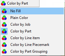
These change the way parts and plates are displayed in the editors, and also the way in which their metafiles (part and plate icons) appear on screen and how they are stored in the database. They affect display not just in the nesting editor, but processing and part geometry editors as well.
In the filled modes, The fill colors of the plate and parts can be controlled via the user options dialog:
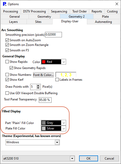
The background color of the graphics windows can also be adjusted (we use a white background for many of the screenshots in the documentation), this is done via the Graphics Options Alt G, though hardware graphics acceleration is required to be on.
No Fill
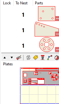
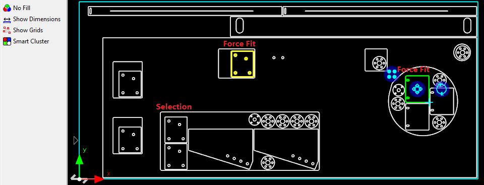
Line drawing of plate and part geometry. Clusters are not distinguishable. Metafiles as still filled.
Plain Color
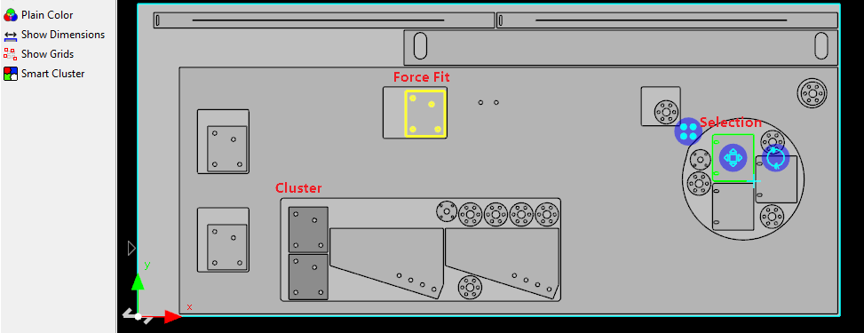
Parts and plate geometry is filled in, making it easier to distinguish holes, and to detect badly drawn parts (open paths). Clusters are colored a little darker so they can be distinguished:

Color by Job, Color by Part, Color by Line Item, Color by Line Piecemark
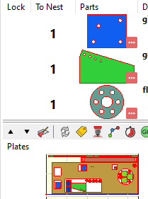
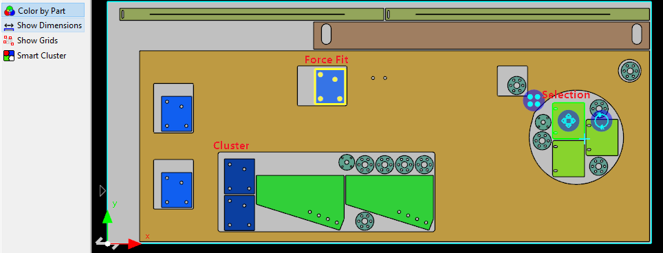
Parts are now colored using a semi-random palette to distinguish based on the criteria selected. Clusters are still a little darker as shown below, but it is not as clear as in Plain Color mode.
You can use the * and / buttons on the numeric keypad to cycle the color palette backwards and forwards to aid in distinguishing similar color parts.
Color By Part Grouping
This is a special view for machine with unloaders, and indicates which parts on a plate have compatible groupings, ie could be stacked on the same pallet. It does not necessarily mean they will be stacked on the same pallet as the pallet may fill up and another pallet(s) may be required.