The StrikeThrough Bridging tool provides two different modes of bridging used for different purposes. Both modes can be used to join multiple geometries or parts in a cluster into a single geometry. You can choose one of the modes after clicking ![]() tool button. You should select geometries or parts (in a cluster) before using the tool.
tool button. You should select geometries or parts (in a cluster) before using the tool.
Bridge joining
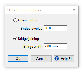
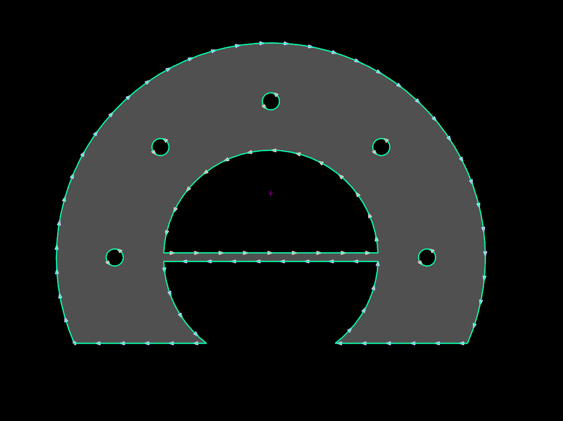
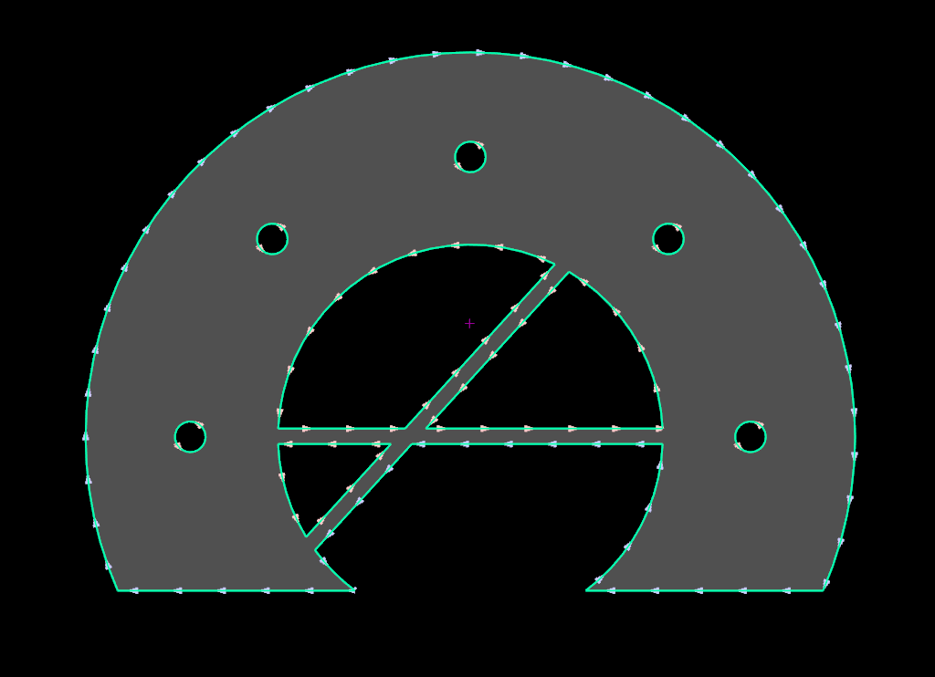
Bridge joining is used to connect one or many closed geometries by creating a bridge with the specified width. When you specified the width of the desired bridge, press OK and draw a line approximately where you would like the bridge center line to be. It is recommended to use the orthogonal drawing mode (F8), but not necessary. Bridge joining is only possible when both sides of the potential bridge intersect the same contours at each intersection.
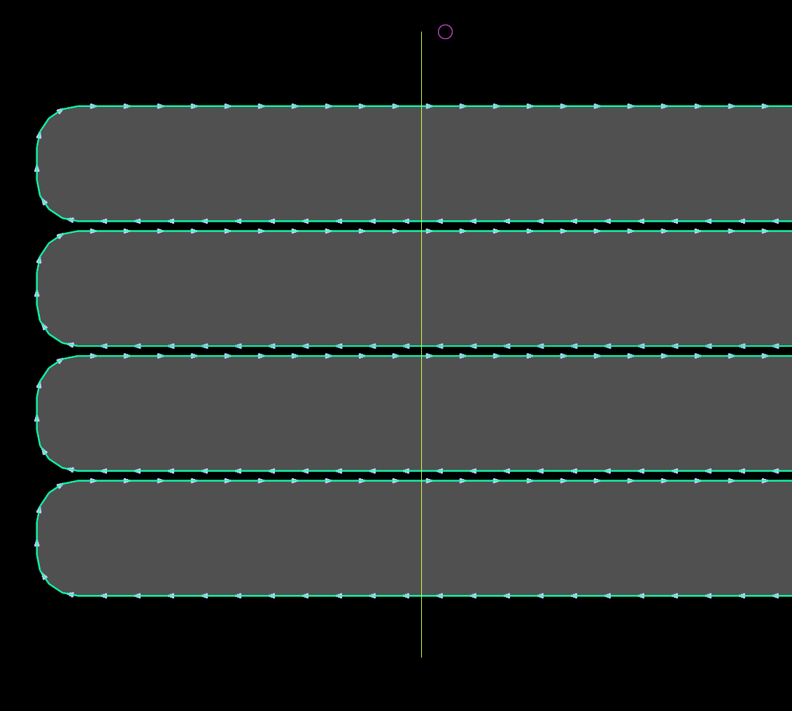
After bridge joining multiple geometries, they become a single closed geometry.
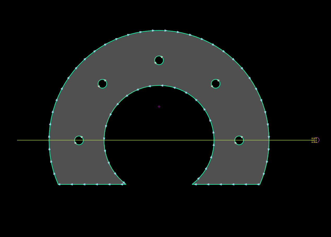
However, this operation may produce new internal cuts as following:
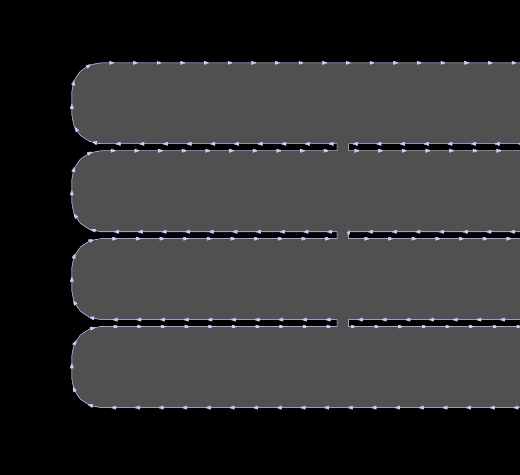
As you can see in the previous example, the existing internal cuts have not been affected by bridging. However, the internal cuts which appeared as a result of previous bridging will be affected by further bridging operations:
This can be used to achieve the following result when a single geometry is connected by multiple bridges:
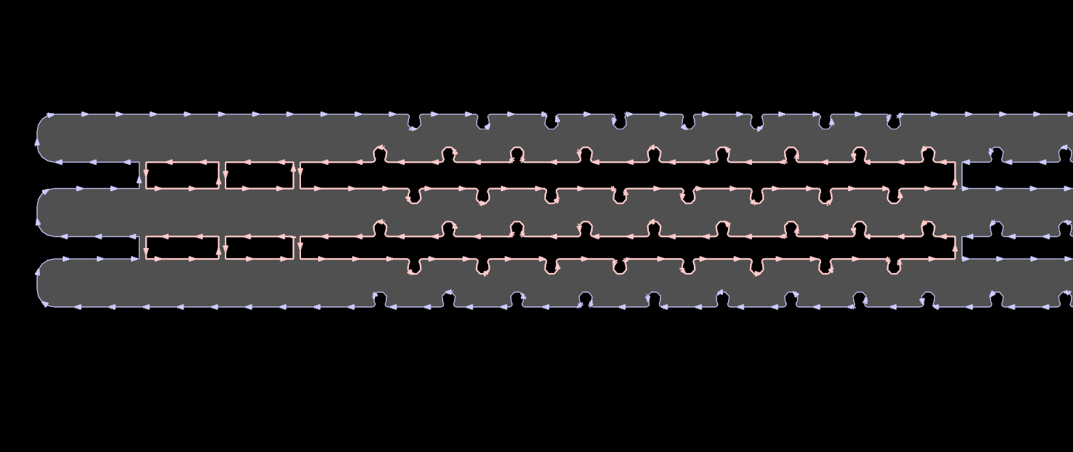
Chain cutting
SmartCluster now provides more automated tools to support this functionality, however in some special cases you may need or want to still use the older functionality
As already mentioned care must be taken when using StrikeThrough bridging because of the potential for plate distortion and poor quality parts. Nonetheless it is an efficient and therefore useful method of nesting parts.
1.In the Nesting editor create an array of the part you would like to bridge cut.
2.Select the array then RIGHT CLICK and select Create & Edit Cluster from the Nesting editor context menu.
The new cluster will be added to the parts list and will be opened for you in the Part Geometry editor.
3.Select all of the parts in the cluster and press the StrikeThrough button on the toolbar.
4.In the StrikeThrough bridging choose "Chain cutting" mode and enter the desired bridge overlap. A value of 0 applies no overlap and the bridge is a straight line. A negative value is used to leave tabs such that the parts will not detach from the plate. A positive value will overlap the cutting path to ensure part detachment. See for information on the use of overlapping when bridge cutting.
5.Use the mouse pointer to draw a line approximately where you would like the bridge lines to appear. Be aware that if you draw the line directly on the edge of the part the bridge will not work - the line must be slightly inside the geometry of the parts. For this reason it may be useful to Clear All Snaps in the Geometry editor.
The bridge line will generally 'snap' to the edge of the parts, depending on the Strikethrough Snap Tolerance that has been entered into the Geometry Options dialog.
6.Click on the Processing editor tab and apply processing as normal.
7.Place the leads at the end of the spine as shown below.

8.DOUBLE CLICK on the plate (in the plate list) to open it in the Nesting editor, and nest the processed bridged cluster as desired.