Glue Common joins parts with a shared cut: one cut line between two parts instead of two. It saves plate and cut length. It is the nesting editor counterpart of Common Line and Common Crop Cutting.
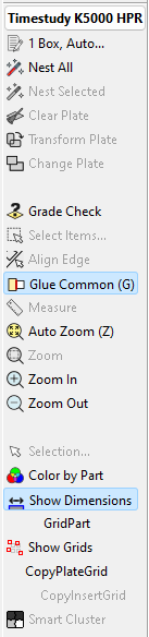
Press G, or click the Glue Common (G) button on the Nesting Editor toolbar, to turn Glue Common on. Press G again to turn it off. Esc first cancels a drag or a picked edge, then turns Glue Common off. Undo and redo do not change whether Glue Common is on.
To glue a part to another part
Glue Common works edge to edge: you pick a straight edge of the part to move, and the edge of another part it should lie against.
1.Turn on Glue Common (G). The cursor becomes a capital G, and the straight edge under the cursor is highlighted.
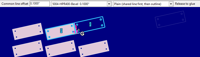
2.Drag that edge onto a straight edge of another part. The part follows the mouse. Near a target edge it turns so the two edges face each other, and lies against it at the common-line offset. The grabbed edge and the target edge are highlighted.
3.Move along the target edge to choose where the part goes. It catches when the ends line up, when the sides line up, and in an inside corner.
4.Release the mouse. The two parts become one cluster with a shared line between them.
You can click instead of dragging: click an edge to pick it (it stays highlighted), then click the target edge. The part is glued where you clicked, and nothing stays picked afterwards. Esc or a click on empty space clears the picked edge.
Only the part whose edge you picked moves. A part with a grain or axis constraint only turns in quarter turns. An edge it cannot turn to face is not highlighted, and dropping or clicking there shows "That part cannot turn to face this edge".
Nothing changes until you release. Esc during a drag puts everything back as it was, and dropping a part back where it came from does nothing. The selection is cleared after a glue.
When the glued position touches several edges at once (an inside corner, the gap between two parts, or a cell going back into its array slot), every one of those edges becomes a common line. The preview shows each of them.
Offset and process
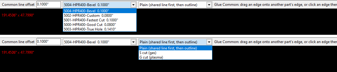
While Glue Common is on, or a common-line array is selected, a strip above the canvas shows the offset between the parts and the cutting process it comes from. The offset is one full kerf of that process.
•Pick a different process in the process list; the offset follows its kerf.
•Type a number in the offset box and press Enter to use another offset. Esc restores the old value.
•With a common-line array selected, changing the offset rebuilds the array.
If no cutting process with a kerf can be found there is nothing to offset by, and the part does not snap.
Cut style
Next to the offset is the cut style, which decides the order the shared cut is made in.
•Two parts: Plain, S or G. Plain cuts the shared line first, then the outline of both parts. S starts on the outside and crosses over halfway along the shared line (usually best for flame). G starts on the shared line and spirals out around both parts (usually best for plasma). See Cluster Pairing: S and G Cuts.
•Three or more parts: the shared lines are cut first, then the outline. Alternate reverses every second shared line to shorten the rapid moves.
The default style for two parts comes from the Common-line Pair Cut setting of the cutting tool. Your pick stays until you change the tool or process. While you drag, coloured, numbered lines on the plate show the cut order of the chosen style.

Cut order and leads
•Holes and voids in the parts are always cut before the common lines.
•Common lines in each direction are cut in a continuous run: the lines already cut only grow at either end, so it is always clear when a part is cut free.
•A common line that ends on a hole starts at the hole edge, with no pierce and no lead.
•Other common lines pierce in the scrap, clear of the cut paths by the pierce allowance.
•Common lines follow their own lead rules and ignore the tool's No Leads for Open Paths and No Kerf for Open Paths settings.
Gluing onto a spine or chain
Drag (or click) an edge onto the spine or a link of a spine or chain cluster. The segment is highlighted, and a dashed outline shows the whole cluster as it will be: the new part slotted in where you drop it, and the parts after it moved along as a block so every part keeps the plate's part gap (Gap Size), part outline to part outline. Release to slot the part in. This is the only way to add a part to an existing spine or chain.
Gluing onto an edge of one of the cluster's parts instead common-lines that part with yours, and the pair goes back into the spine or chain in that part's place. If that is not possible (for example the cluster would leave the plate or overlap another part), a one-line notice says why and the pair is left beside the rest of the cluster.
Gluing onto a crop line
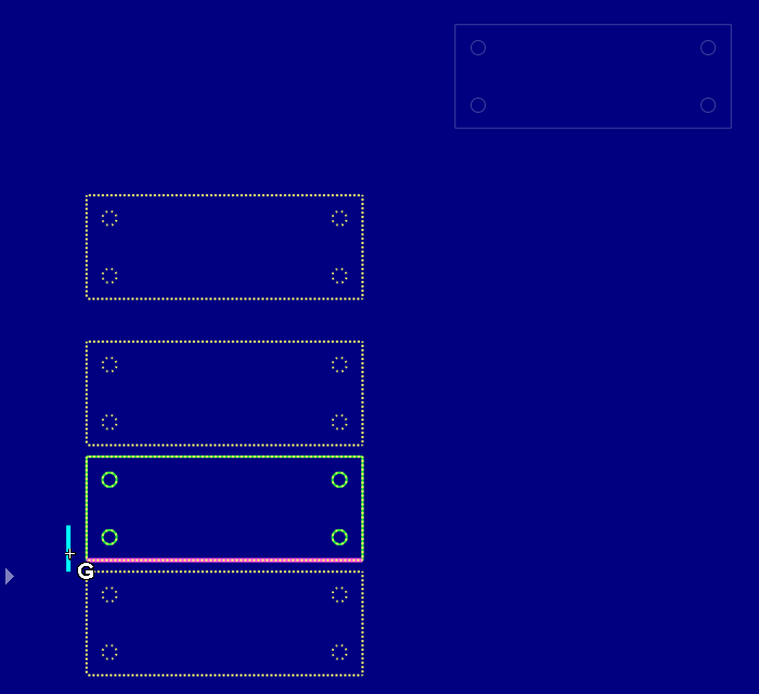
The plate crop line, and the crop line of an existing Crop Cut cluster (including its straight run to the plate edge), are glue targets too, where they run straight along the plate (horizontal or vertical). A crop line that turns a corner cannot be glued to. Drag (or click) a part edge onto one: the crop segment is highlighted and a dashed outline shows the result. The part's edge goes onto the crop line itself.
•On the plate crop line (Release to make a Crop Cut): the part becomes a Crop Cut cluster, and its crop replaces the plate crop on that line.
•On a Crop Cut cluster's crop line (Release to join the crop): the part joins that crop where you drop it. It is only pushed along, to the plate's part gap from the part next to it, if it is closer than that.
If the part cannot go there (for example it would leave the plate or overlap another part), no outline is shown, and releasing or clicking gives a one-line notice with the reason; nothing moves. One undo reverses the whole glue.
[SCREENSHOT TO COME: glue-common-crop-cut.png - plate crop segment highlighted, dashed outline of the resulting Crop Cut]
Common-line arrays
A common-line array can be dragged whole and glued by an edge, and is also a glue target. Once glued to another part it becomes an ordinary common-line cluster and is no longer an array. Arrays of a cluster with more than one cell cannot be dragged with Glue Common.
To take a part back out of a glued cluster, hold X and drag it out; see Pulling Parts Out of Clusters.
If a part inside a common-line cluster is edited after the cluster was made, the cluster is drawn with an orange outline and a "!" badge. Right-click it and choose Regenerate Common Line Cluster to rebuild it from the edited parts.
[SCREENSHOT TO COME: glue-common-out-of-date.png - out of date common-line cluster with the orange outline and "!" badge, and the Regenerate Common Line Cluster menu item]
Check the sequence
With the user setting Order New Processes by Rules and Warn On Bad Sequences on, the post processor checks the cut order and writes a BAD SEQUENCE warning into the NC program for any cut that is out of order. Fix the order in the Sequence Editor, or rebuild the cluster.
[SCREENSHOT TO COME: glue-common-bad-sequence.png - BAD SEQUENCE warning in the NC program for a common-line cluster]
See also Common-Line Arrays, Pulling Parts Out of Clusters, Align Edge, Nest Editor Shortcuts.