In this section
Moving a Selection of Multiple Parts
The Basics!
The most basic way to nest a plate is to manually drag parts into the plate. Just Left Click on the part using the mouse and (holding the mouse button down) drag the part onto the plate that has been opened in the Nesting Editor. (If a part is dragged onto a plate open in the Processing Editor, it will jump back to the Nesting Editor automatically)
•Grade Override You will only be able to nest the parts if they are of the same material and thickness as the plate. If the thickness is the same, but the grade differs, you will be prompted as to whether you want to allow Grade Override , this allows for example, Gr250 parts to be nested onto a Gr350 plate. Auto Nesting will not permit Grade Override.
•Bump Nesting If a part is slightly too close to (or overlapping) the edge of the plate or another part then PrimeCut will attempt to "bump" it into a valid position. This is useful when you want to nest a part as close together as possible because you can overlap them slightly and let PrimeCut nudge them so they are spaced at the minimum distance.
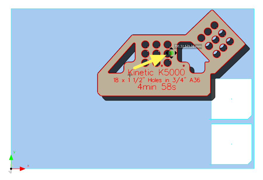
•Floating Parts Part Inserts that do not fit are called Floating Parts, see the red part in the images below. They are shown with a red boundary, and if filled parts view is active have a "shadow" beneath them, as if they are floating above the nest. If you want to fit parts into a space that is only slightly too small you can use Force Fit. Floating Parts are not truly part of the nest:
NOTES
When the plate is saved, the floating parts inserts ARE NOT SAVED.
No Processing or Processable Geometry is available from these parts.
When selecting multiple parts, if Floating Parts are within the selection window they will be added first and exclusively to the selection (the intent being that you probably want to do something with them, rather than the fixed parts "below" them).
Often you may wish to move a previously nested part. To move a part, first select it, then click and drag the Move Handle near the center of the shape (You can use the Insert Point Handle as well).
Part Insert Handles
The part has been dragged to where it no longer fits, it is now Floating. It can be dropped here though by releasing the mouse, and may "bump" into a nearby fit position, unless the overlap is too great.
The part position may also be set via its properties: Right-click on a selected part, choose Properties from the drop-down menu and examine the Insert point X and Insert Point Y properties.
Note: In order to set the part position exactly through its Insert point properties, you should set the part as Force-Fit first, otherwise PrimeCut is likely to disturb the part slightly to conform to its nesting approximation.
Moving Parts with the Keyboard
You can also move the select part (or parts) around with the keyboard. The arrows keys can be tapped to nudge the part in minimal increments, or held down to move the part continuously in the direction of the arrow keys. The part will keep moving until it hits an obstacle (another part or the dge of the plate- gap settings are maintained so the part will stop before it actually makes contact).
You can Throw a part also, using the Alt+Arrow Keys. This will immediately "teleport" the part in the direction of the arrow key as far as it can go until it hits something. If it is hitting something already it will try to jump to the other side of the obstacle.
Using Spacebar to Float or Fit selected parts
When parts are selected you can hit the spacebar to toggle their floating status in the nest. ie if they are in the nest, spacebar will float (unnest) them, if floating they will be fitted back into the nest (if possible, Primecut will jiggle them a little if necessary). A common use for this is to force primecut to reapply part processing to the nest when unwanted processing changes have been made on the plate; ie "reverting part processing").
To rotate a part, click and drag the Rotation Handle to the side of the shape. You can free rotate the part to any angle. If Shift is held down before dragging the rotation handle, then the rotation angle will snap to multiples of 15 degrees, enabling easy setting of 30, 45, 90 and 180 degree rotation angles. If a part has been free-rotated to an indeterminate angle and you want to "square it up", say to 90 degrees, then again holding down Shift and re-rotating the part can achieve this. The exact rotation angle can also be set directly by right clicking on the selected part and choosing Properties, and setting the Rotation parameter.
Rotating the part by a lever.
Several parts may be moved at once by selecting several parts together, using either a selection rectangle (dragging the mouse with the left button depressed to define a selection region), or by using selecting multiple parts using the Shift and Ctrl keys, see below.
You can also rotate a cluster selection (as a whole) by dragging its rotation handle.
Rotating Parts with the Keyboard
The square bracket Keys [ and ] can be used to rotate the selection by 90 degrees counterclockwise and clockwise respectively.
Holding down the Alt key while doing this changes the rotation increment to 5 degrees.
Other Techniques
Parts can be Arrayed easily.
Clusters can be created including Automatic Self-Clusters.