In this section
In this section:
Troubleshooting NC Preview Display
See also
Advanced Post Processor Tweaks
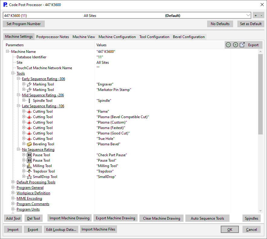
The Machines dialog contains the settings for each machine that are used to generate valid NC code for that machine. For this reason it is critical that you do not change settings unless you are certain of what you are doing.

▪The drop-down box at the top of the screen allows you to select the machine you want to view settings for. The +/- buttons to the right of this should not be used except by Kinetic staff, they will add a new machine or make an existing one obsolete.
▪Set Program Number allows you to set the next program number for the currently selected machine. There is also a code in front of the number that indicates which machine the program is for. This code is defined by the Auto File Name Format which is stored under Program General.
▪The No Default and Set as Default buttons can be used to treat all machines equally or set up one machine as the default. This means that any part loaded into a workorder will default to being processed by the selected machine.
▪Add Tool and Delete Tool are used to add and remove tools from the machine. Once again this should only be done by Kinetic staff, however 'Pause Tools' are safe to be added by non-Kinetic staff.
▪Spindles will display the spindle bit settings for the selected machine. This is the same table that can be accessed via the Process Geometry Dialog.
▪Import can be used to quickly import a new set of machine settings, which will generally be supplied by Kinetic.
▪Export will save your current machine settings to file.
Most of the settings accessed through the Machines dialog should not be changed by the user. The few settings that may be changed are discussed below.
Tools and Inserting NC Processing Codes
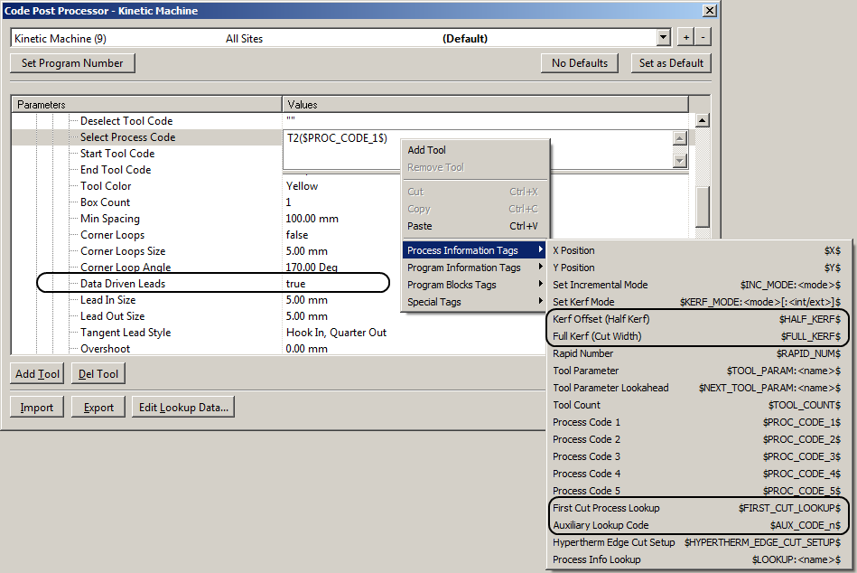
This drop-down shows all the tools that the selected machine has. Selecting a tool from th list shows a drop-down list of settings for that tool. The options in the list vary depending on the tool selected. All tools have excerpts of NC tool codes in their list of properties for selection, starting and stopping. These codes can make reference to the specific process found in the costing data tables for processing defaults (see Cost ID Setup). Right Clicking in one of these code fields allows us to insert a tag to insert into the NC code at that point the corresponding field in the processing data (if Data Driven Leads is set to true). Under Process Information Tags you can refer to any of the first five or auxiliary process codes for this Cost ID. Other useful parameters can also be accessed, such as the Half and Full Kerf offsets you set. Tools you want to have the Data Driven Leads described above need this field set to True. Another useful parameter is the First Cut Process Lookup, which references the Process Code 1 of the next cut in the schedule.

Other properties of a tool that can be changed include
▪Color- The color used in the processing editor to represent this tool, (When the processing isn't data driven (see Process data ))
▪Box Count - The number of this tool that can be parallel (MultiBox count)
▪Min Spacing - The closest the parallel boxes can be to each other
▪Corner loops - whether the tool requires a corner loop to generate a sharp corner.
▪Corner Loops Size - how far from the corner the loops go.
▪Corner Loop Angle - the angle larger than which no corner loop will be applied.
▪Data Driven Leads - Whether the process specific data from our Process data is used for generating the initial leads.
▪The default lead-in, lead-out and overshoot values if Data Driven Leads is selected as false (or "Use Process Data for Leads" switched off in the processing editor dialog)
▪Kerf (offset) distances and pierce allowance if Data Driven Leads is turned off.
▪Bit Table (see Milling Bit Table)
▪Tool Parameters - used when a tool can have multiple parameters/be used in multiple ways, such as a chamfer tool.
In this section
Troubleshooting NC Preview Display