When applying processing to parts or plates, the Processing Options Dialog provides a number of options for controlling particularly how leads attach.
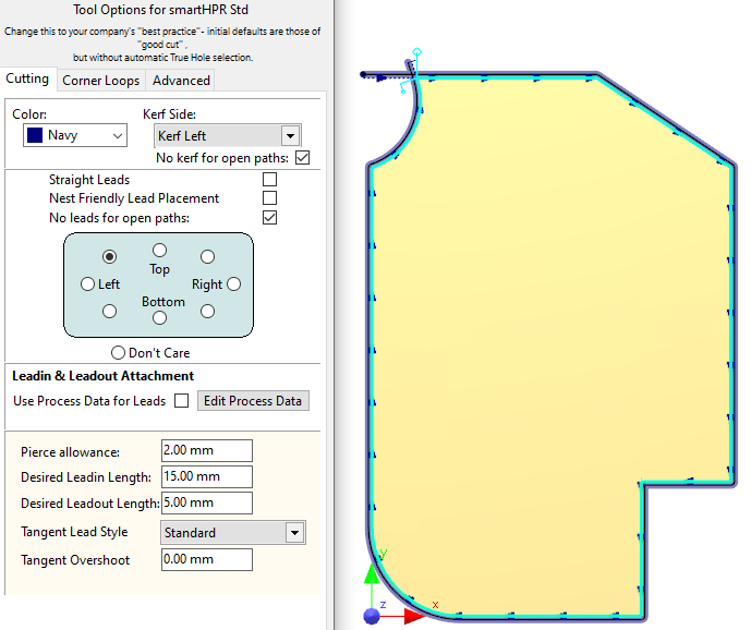
In this example with lead tendency Top-Left, the leads have attached to the corner nearest the top left.
Some of the above options are explained here.
The Cutting tool will have its own set of lead placement options which control in fine detail how leads are applied; you can edit these temporarily on the Advanced tab, or set permanent defaults by editing them in the Machines section.. Some of these are readily editable via the processing options dialog here, and some can be overriden with Process Data .
Inhibit Arc Leadins If checked will not apply arc leadins. On disks and parts without corners this results in hook leadins or 45 degree line leadins; arc leadins are inhibited. see also Kerf Settings- Gradual Kerf Takeup
Inhibit Hook Leadins If checked hook Leadins are inhibited. If this and Inhibit Arc Leadins are both checked only Straight leads are possible. If this conflicts with the Tangent Lead style, it is possible leadins will not be placed at all.
Nest Friendly Lead Placement Uses special hook leadins and 45 degree leadouts on corners when processing parts to making nests more efficient. See Nest Friendly Leads for more information.
No Leads for Open Paths If applying cutting processes top Open Paths then don't apply leadins or leadouts
Left, Top, Right etc Leadin Attachment tendency, where on the geometry you would prefer the leads. More useful when processing plates.
Use Process Data for Leads If Checked will look up the Tool, Grade and Thickness (and optionally Plate Condition and Geometry Size) and attempt to get its Pierce Allowance, Lead lengths, overshoot, pierce type, Tangent Lead style etc from there:

Sample Process Data
Pierce Allowance (Optionally looked up from Pierce Diameter in the Process Data) Is the effective approximate diameter of the pierce hole. Combined with the Pierce Margin and Don't Pierce On Kerf settings below this is used to reduce the chance of the tool colliding with the pierce dross while the other path is being cut, and to prevent the pierce from gouging adjacent parts.
It is also used when pre-piercing with the drill as the default diameter to look up in the spindle allocation table; but it can of course be overriden.
Pierce Margin This Tool Setting is added to half the Pierce Allowance on External Cuts to get the minimum allowable distance of the pierce point to the part geometries, or if Don't Pierce On Kerf is set, to the kerf of the other cuts.
Don't Pierce On Kerf (Tool Setting) If True, will prevent the pierce from overlapping the kerf of this and other cutting processes, only effective on external cuts.
NOTE Pierce Margin and Don't Pierce On Kerf do not affect internal cuts as of version 4.132.649 (#18806). Reason: Small internal cuts sometimes need to push the pierce closer to the edges than otherwise desired, simply to make the leadin fit.
The images below show the effect of Pierce Allowance, Pierce Margin and Don't Pierce on Kerf. The Pierce Allowance is the diameter of the outer points on the pierce "star" as shown in yellow. Look carefully and you will see that the Pierce Allowance Ball is slightly offset perpendicularly from the end of the leadin, by one kerf offset, as that is the true center of the pierce point when cutting.
 Default Settings allow the pierce to overlap the cut, so long as it does not interfere with the part |
") Don't Pierce on Kerf (EXTERNAL CUTS ONLY) |
") Pierce Margin (EXTERNAL CUTS ONLY) |
") Don't Pierce on Kerf and Pierce Margin (EXTERNAL CUTS ONLY) |
Desired Leadin Length This is the requested length of the leadin. In practice the system may be unable to find a placement of the length required and may have to shrink the lead to make it fit.
Desired Leadout Length Similar to the above but for leadouts.
Tangent Lead Style (TLS) Determines how the leads will attach (leadin and leadout style) when there is no corner to attach to, see below.
Tangent Overshoot This OverCut (or (UnderCut if negative) will be applied, but ONLY when applying leads away from a corner, ie when applying a Tangent Lead style.
A number of Cutting Tool settings also affect how leads are automatically applied:
•Pierce Centrally On Small Holes
•Nest Friendly Leadin Placement